Grantham Cabin Diagram: This project appeared unexpectedly when the Signal Electricians donated the former Grantham signal cabin diagram to our workplace, for use as a display item. A broad request for items to display in the Control Room resulted in several items including signs, signal relays and the Grantham cabin diagram. It had been attached to the wall of the signal cabin for many years, out of use, and mainly acted as a roost for local pigeons so it was not in a great state.
cabin diagram Description and brief history.The line from Ipswich was extended west to Helidon in 1866 passing through the site of Grantham. Grantham station appears to have opened in 1875 when a platform and signals were provided, a siding was added in 1878. In 1885 Grantham was classed as a Stopping Place between Gatton and Helidon however in 1913 it opened as an Ordinary Staff station. The line between Gatton and Helidon was duplicated on Monday 16th February 1914. An interlocked signal cabin was provided at Grantham in February 1914 and was likely to have been commissioned the same day.
A small Type 1 signal cabin building was located on the platform at the Ipswich end to house the twelve lever interlocking machine used to operate the six semaphore signals provided, the siding points and crossovers. 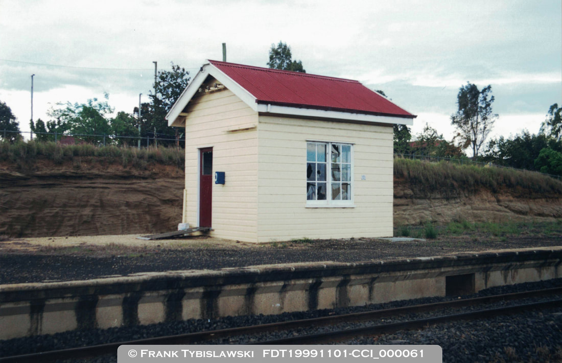
By 1992 the signalling at Grantham, and at many other stations from Wulkuraka to Grantham (excluding Grandchester and Yarongmulu) had been altered with colour light Home and Starter signals installed. The signal cabins remained and were electrically released by the Train Controller when shunting was to take place. When shunting was to take place the signal cabin lever frame was cut-in allowing the Station Officer to operate points and signals as required. When the signal cabin was cut-out the colour light Starter signals were controlled by the Train Controller, and the colour light Home signals functioned as automatic signals.
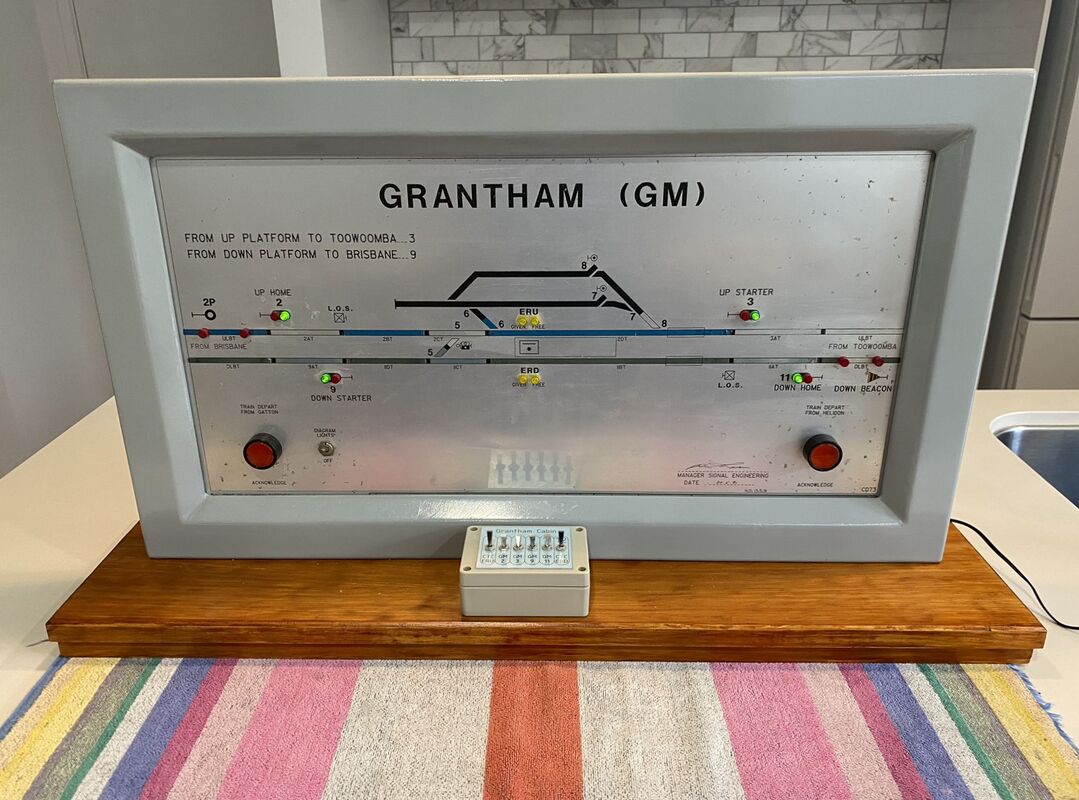
The cabin diagram at Grantham was provided at this time to repeat the indications of the Up and Down Home and Starter signals, the Up and Down Approach tracks, and the Up and Down Electric Releases (which could be independently given as required). The cabin diagram was manufactured by Ventura Projects and has the bare minimum of indications provided.
The Station Master at Grantham was withdrawn on 31st July 1992 with an Area Supervisor (based at Helidon) working the signal cabin when required.
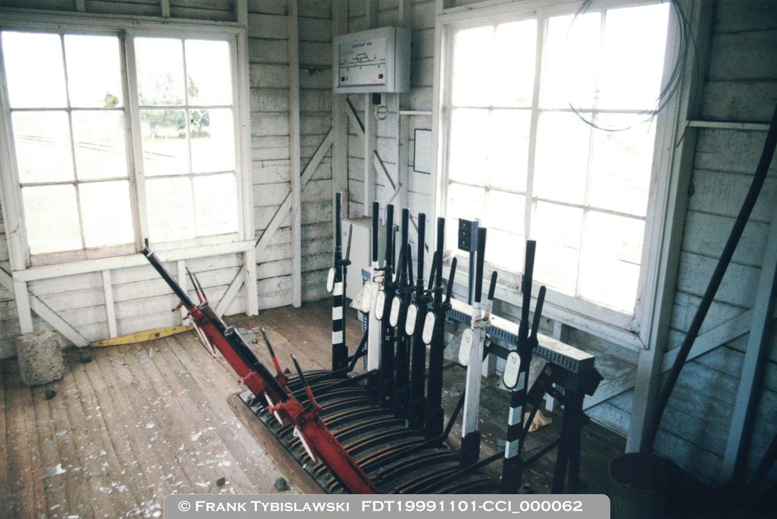
By September 1999 the siding points and crossovers had all been disconnected however the signal cabin, lever frame and cabin diagram remained and had not been fully decommissioned. By January 2000 the signal cabin had officially been decommissioned and the cabin diagram had been removed. The lever frame remained but all wiring to control the signals had been removed. In January 2001 the lever frame was removed leaving the building empty. By 2015 the obsolete signal cabin building and platform were demolished.
|
restoration
The cabin diagram was in poor condition, covered with bird droppings and dust from many years of little or no use. The diagram was removed from the metal frame and cleaned with a variety of products; it is much cleaner but some marks could not be removed.
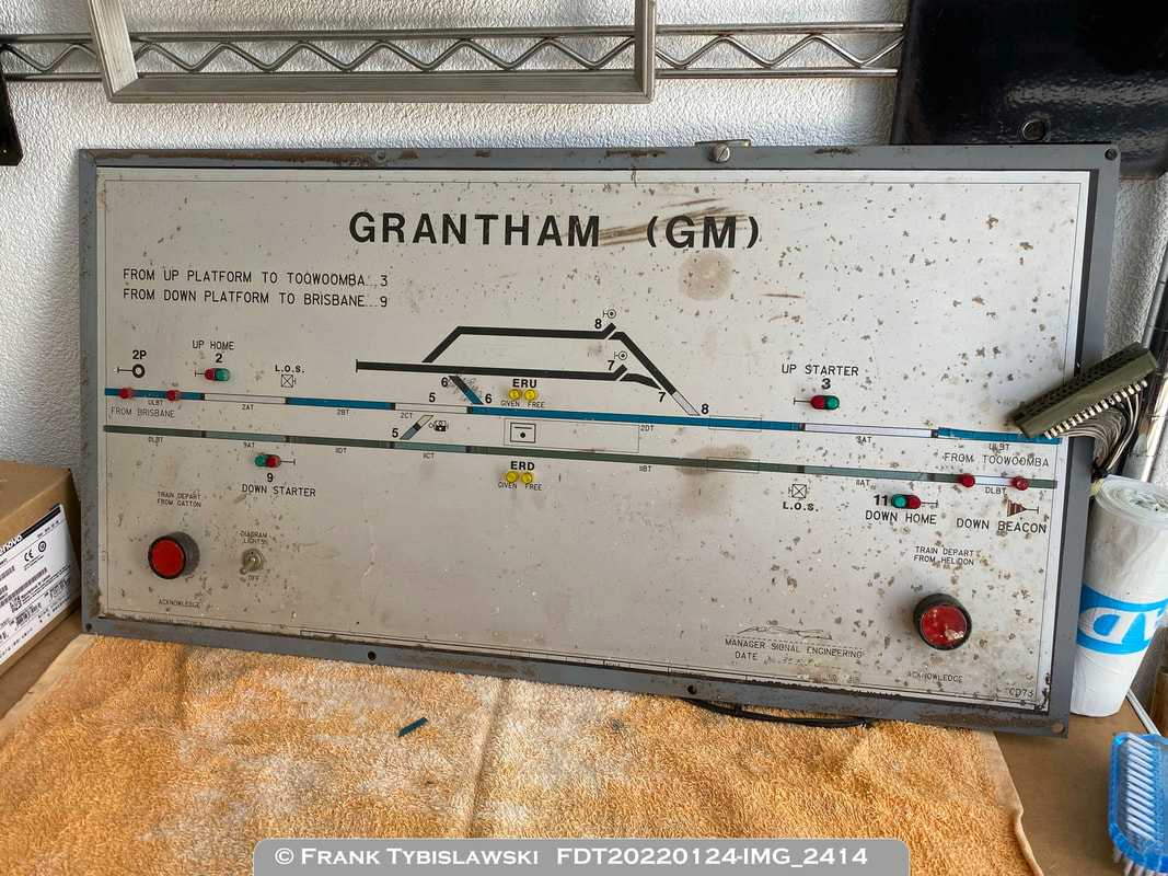
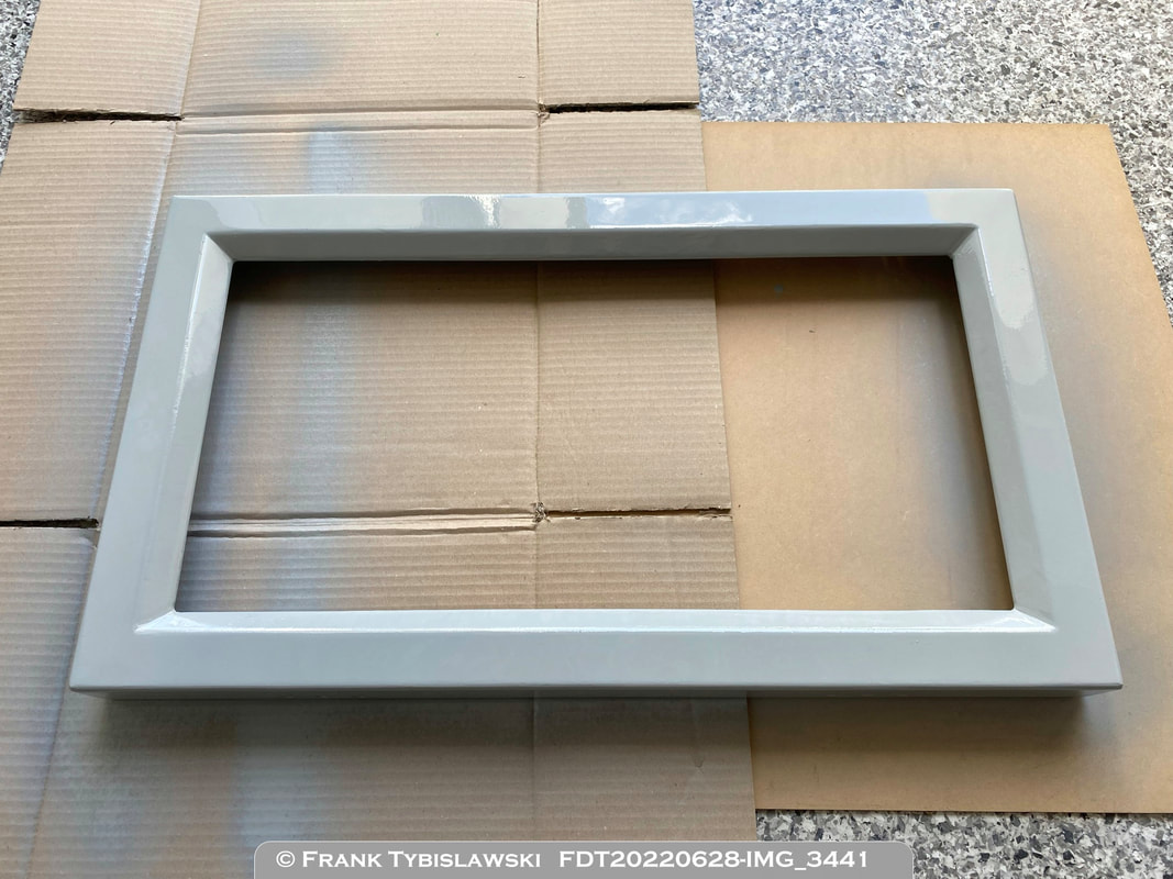
The metal frame was in reasonable condition but the paint was blistering from rust under the paint. It was decided to sand the metal frame back to remove the rust then repaint with a similar colour grey paint.
The cabin diagram was originally a metal box with a hinged front face which could be opened to access internal wiring. Only the front face portion was donated which presented an immediate problem - how to mount or display this part without the rear portion which would normally be attached to the wall. A sturdy wooden plinth was manufactured and the holes for the hinges re-purposed to hold the metal frame to the wooden plinth resulting in a sturdy and stable base. The cabin diagram can now be placed on a table, bench or wide shelf with no risk of it falling over. The wooden based was also stained an appropriate colour.
Rather than just having a display item running a program to sequence the LED indications, an interactive option was included to simulate the signal cabin being cut-in or cut-out, with trains obeying signals as set by the operator. While the original lever frame had twelve levers, it was decided that only the six relevant to the signals and Electric Releases would be added. This simplified the wiring, programming and costs involved. Miniature interlocked levers were out of the question so two-position switches were used with the program determining if they are operated in the correct sequence. A switch operated out of sequence will do nothing and needs to be returned to its former position before trying again. 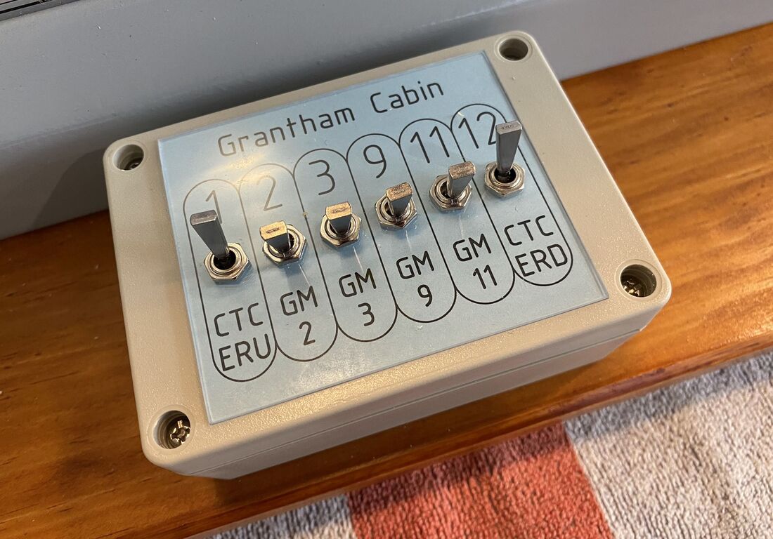
A section of plywood was added to mount the Arduino (with screw terminal shield) and relay board on, and the existing resistor board was also re-mounted. All existing wiring was long enough to be relocated and re-terminated, new wiring was added, and cable ties used to hold everything neatly in place.
The buzzer was removed as it was not needed for the simulated operation and would have been an annoyance in the workplace where the diagram is on display. 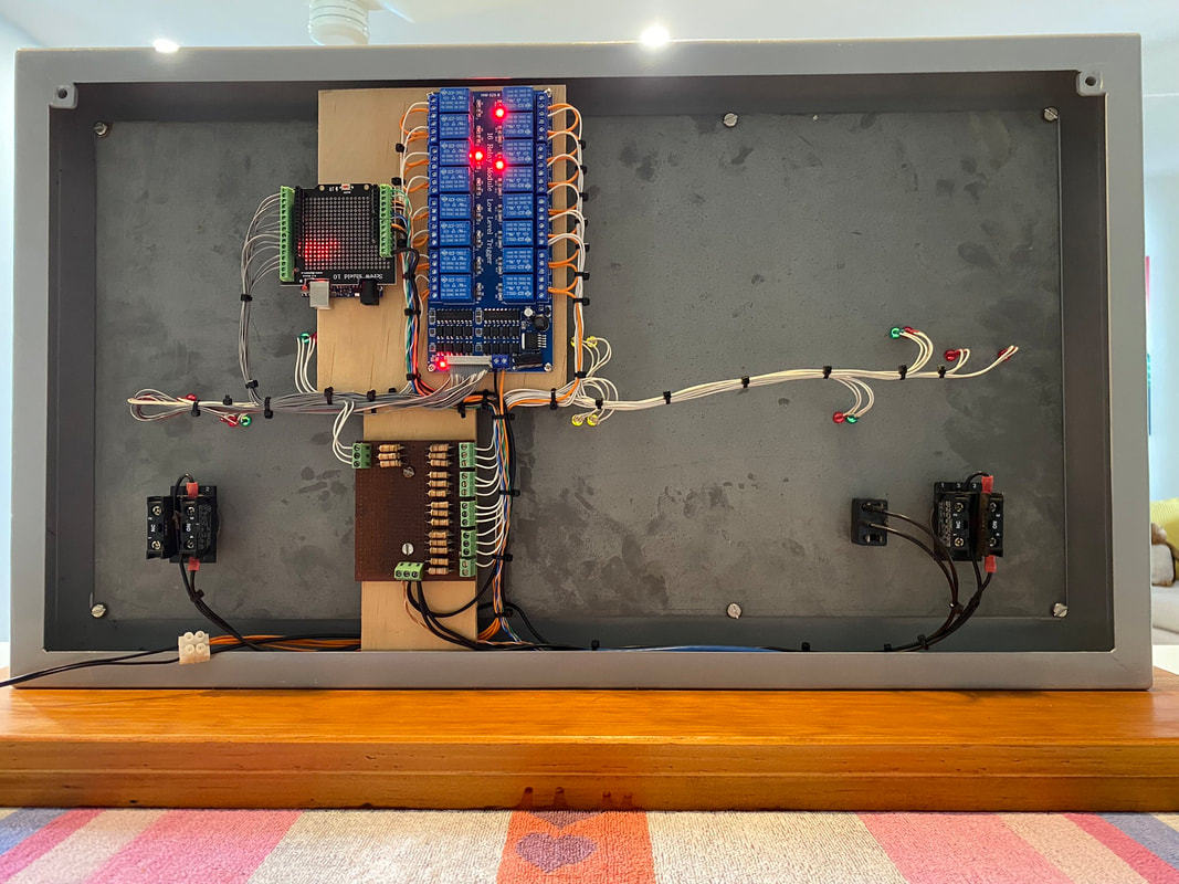
|
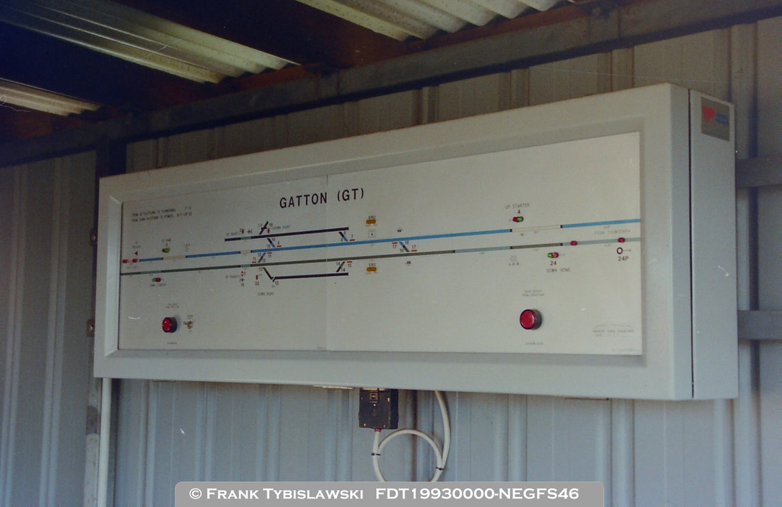
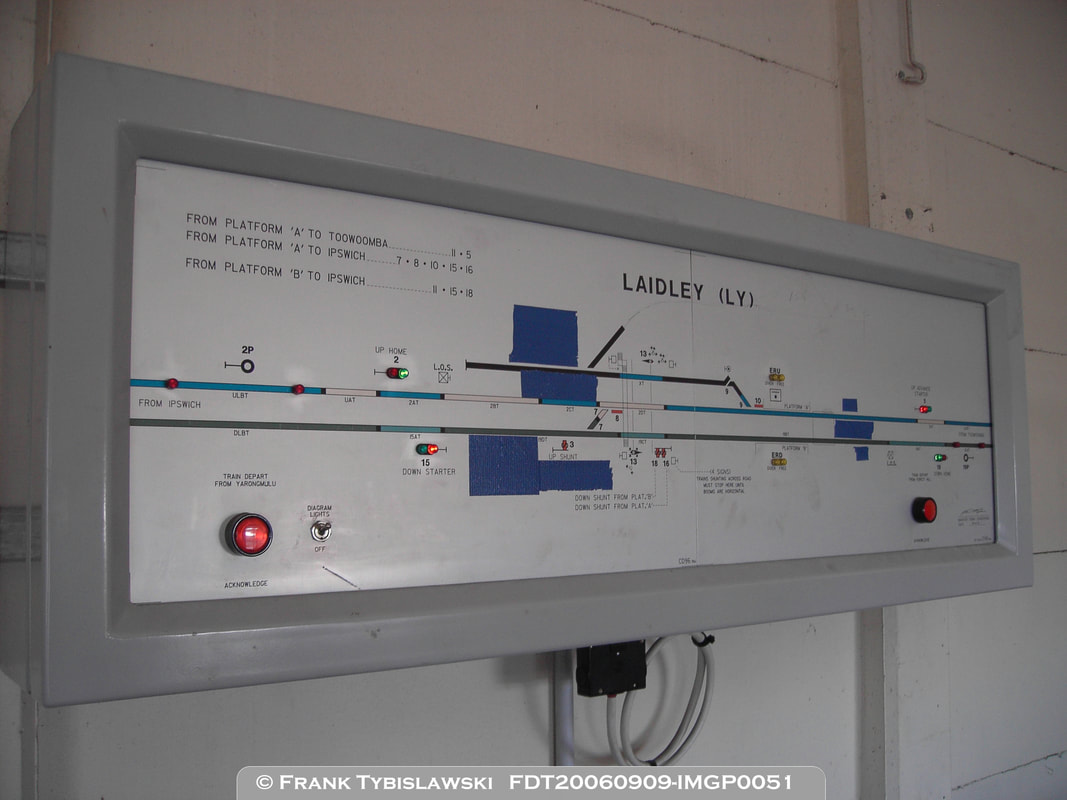
Similar cabin diagrams existed at Laidley, Gatton and Forest Hill and were all installed around the same time. They were built by the same supplier and have similar features, although the physical size depended on the station layout. The Gatton cabin diagram is in a private collection, the Forest Hill cabin diagram is on display at Swanbank and the Laidley cabin diagram appears to have been stolen.
|
|
