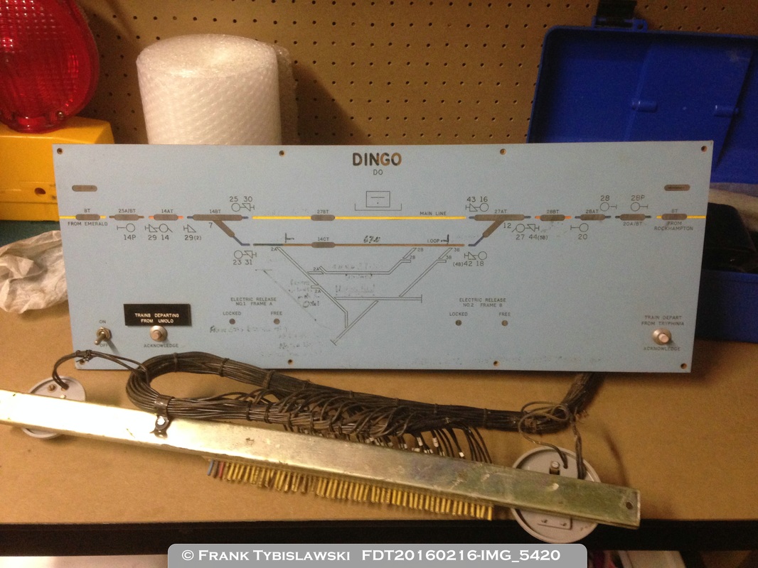
Dingo Panel Project: This project involves the restoration of a former Queensland Railways mimic panel. The panel came from Dingo station (Central Queensland) and is of an unusual type having no control over points or signals, but merely indicating track occupancy and ground frame status.
Panel Description and general information about project.I first became aware of Dingo panel in 1996 while on a trip through Central Queensland. We stopped at Dingo for lunch and I was able to see the panel inside the station office through a window. Years later I was at Dingo again but the station was closed at the time so I could still only see it through the window. I could see that it had no switches except to turn the panel indications on and off, and to acknowledge the approach of a train from the east or west.
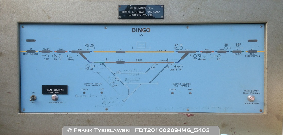
Dingo panel was provided in 1980 when CTC was commissioned between Port Curtis Junction (Rockhampton) and Tolmies including the branch lines to Laleham, Kinrola and Gregory. I later read a reference to this CTC installation where it mentioned the Dingo panel, and also suggested a similar panel was to be installed at Bluff - but I have no idea if this ever happened or not. I recently learnt that a similar mimic panel was installed at Duaringa at the same time.
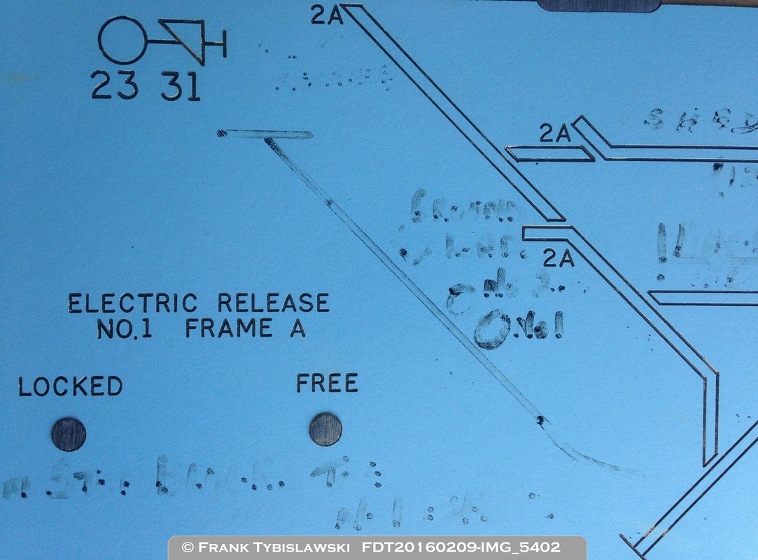
Dingo panel is quite small, measuring only 80 cm by 40 cm, so it would be one of the smallest mimic panels used in Queensland. It has remained virtually unchanged since installation with only one minor change visible. In the bottom left hand corner a black plastic label has been stuck onto the diagram reading "TRAINS DEPARTING FROM UMOLO" above the acknowledge button. 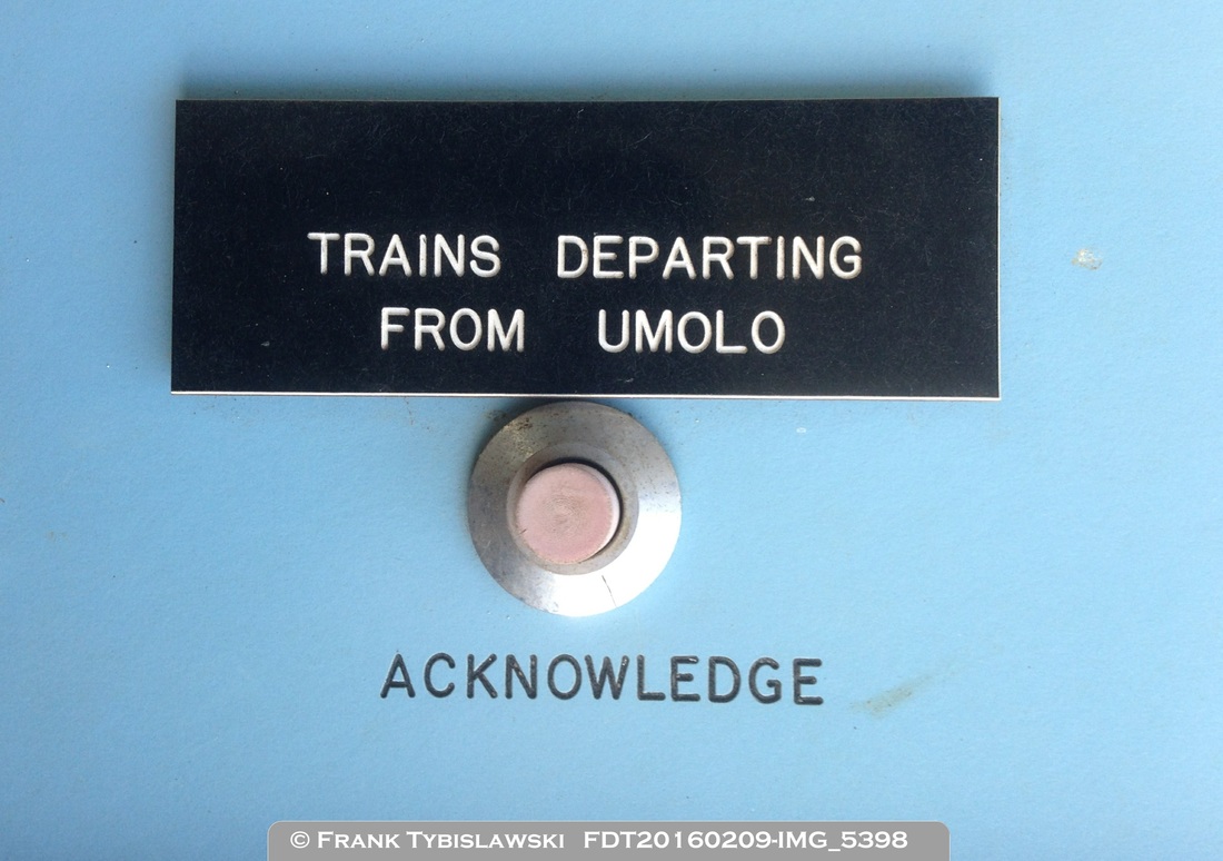
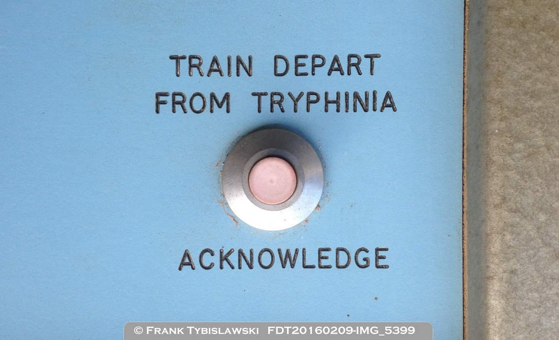
When CTC and the Dingo panel was installed the next station to the west of Dingo was Parnabal. Umolo opened as a crossing station two years later in 1982 and this modification would date from then. No doubt under the black plastic label the original words "TRAIN DEPART FROM PARNABAL" would be engraved on the panel to match the wording on the right hand side of the panel which adjoined Tryphinia station.
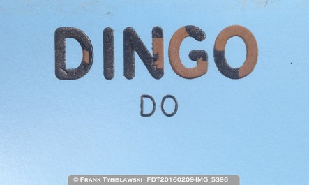
The panel is in remarkably good condition considering its age (36 years old in 2015) and shows little sign of wear and tear. Where the blue plastic has been engraved the paint used to colour the engravings has lifted off in places. This is most evident where the station name "DINGO" is engraved at the top of the panel and black paint has fallen off.
The other area where the panel shows signs of wear and usage is on the face of the panel where a black permanent pen has been used to draw in the sidings not shown on the panel. There also appears to be some words or instructions regarding the operation of the Ground Frames. The black pen has faded and is now almost impossible to read. Hopefully the black pen marks can be removed with some cleaning fluid to restore the original finish.
|
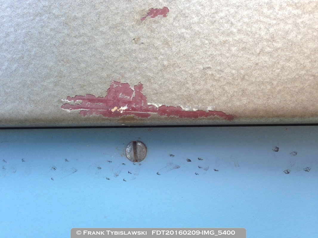
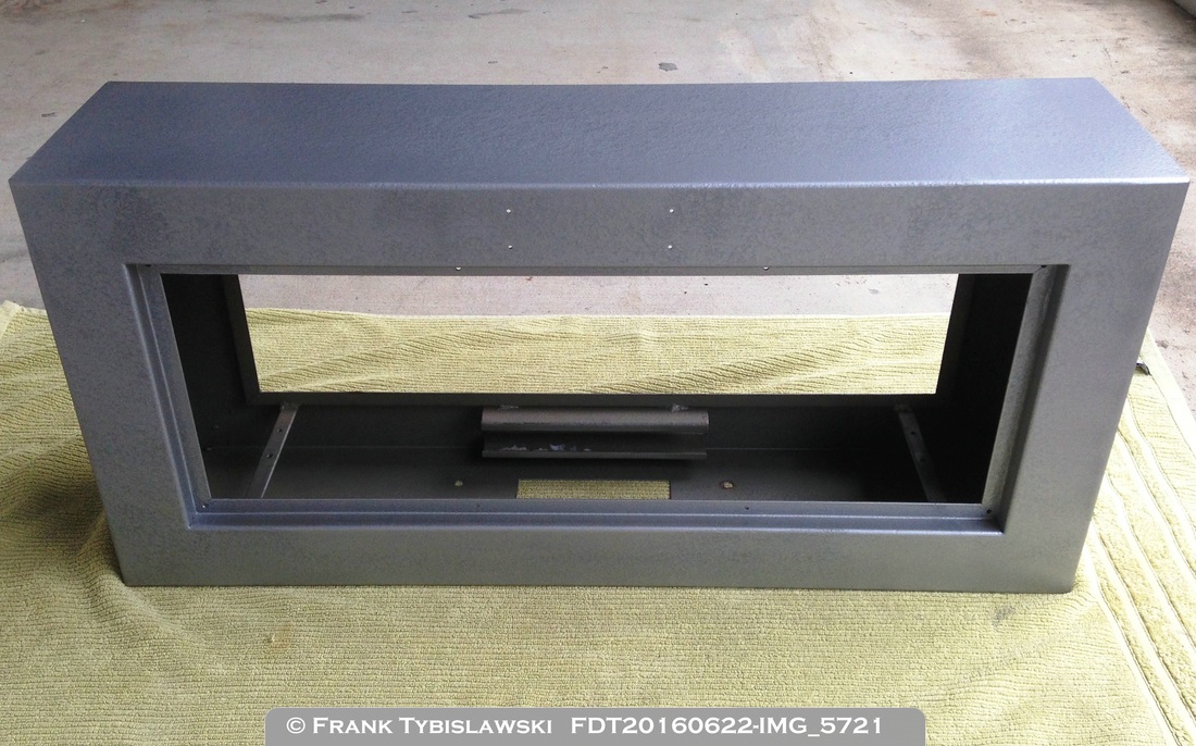
The metal framework of the panel is in good condition but the paint has been scratched in places and there is some minor rust appearing in places. The plan is to sand the paint back and re-apply a new metallic paint finish.
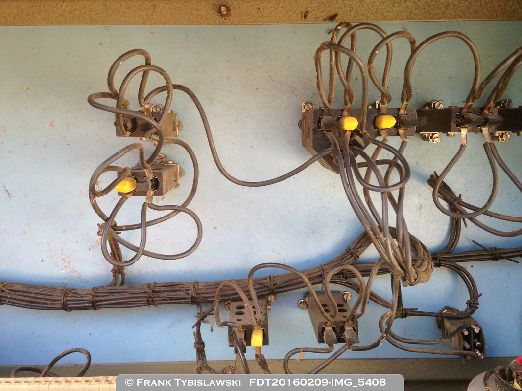
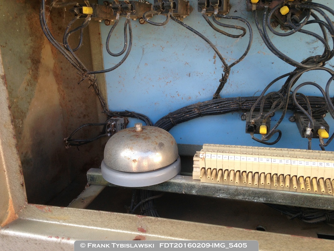
At the back of the panel everything is almost complete, but very dusty and dirty. All the 24 volt bulbs are in place, but these will be changed to 12 volt lamps or LED equivalents, both of which I already have. 12 volt lamps would be more authentic, but the LED variety is more reliable. The wiring is all in good condition with only one broken wire visible during a recent inspection.
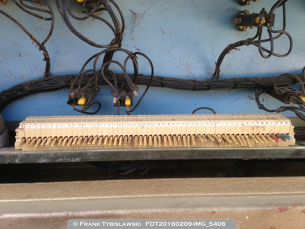
The wiring is all terminated on a connection strip at the bottom of the panel which will make testing very easy after each termination is tested to see which lamp it illuminates. Initially I will select a number of lamps to illuminate to 'simulate' how the panel would have looked when in use. At a later date I may incorporate computer control to simulate the movement of trains through Dingo.
One of the bells which rang to indicate a train was approaching Dingo is present and in good condition. It's probably a 24 volt bell so I don't yet know if this will work with a 12 volt system. The other bell appears to be partly missing, but I have not yet fully investigated this.
The project, with no set timeframe, will follow the steps as outlined below.
|
stage 1 - disassemblyThe first part of the project was quite simple, disassemble the mimic panel into its various components ready for restoration. The makers plate was removed, followed by the blue diagram and the connection strip in the back of the panel. Most bolts came loose quite easily, but a couple have stared to rust. All existing bolts will be reused to save finding replacements of the same size. The 24 volt lamps were also removed and a couple of broken wires were found, but nothing too difficult to repair. An interesting feature of the blue diagram is that it is made from a laminated plywood with a blue plastic layer on each side, this was then engraved for the various details on the panel.
|
|
stage 2 - refurbishmentWith the panel broken down into individual components initial restoration was able to commence. The Westinghouse makers plate is made from plastic which is engraved on the back, has the lettering painted white, then a black background painted over it on the reverse side. Some of that black paint was damaged so the rear of the plate has been re-sprayed with black paint to restore it.
The blue panel surface has been cleaned with a variety of products to remove the pen marks. Whiteboard cleaner was not effective so a stronger product was used. A considerable amount of rubbing was required which has almost completely removed the traces of black pen. The photo below shows the same area in the image above with the black pen marks almost completely removed. 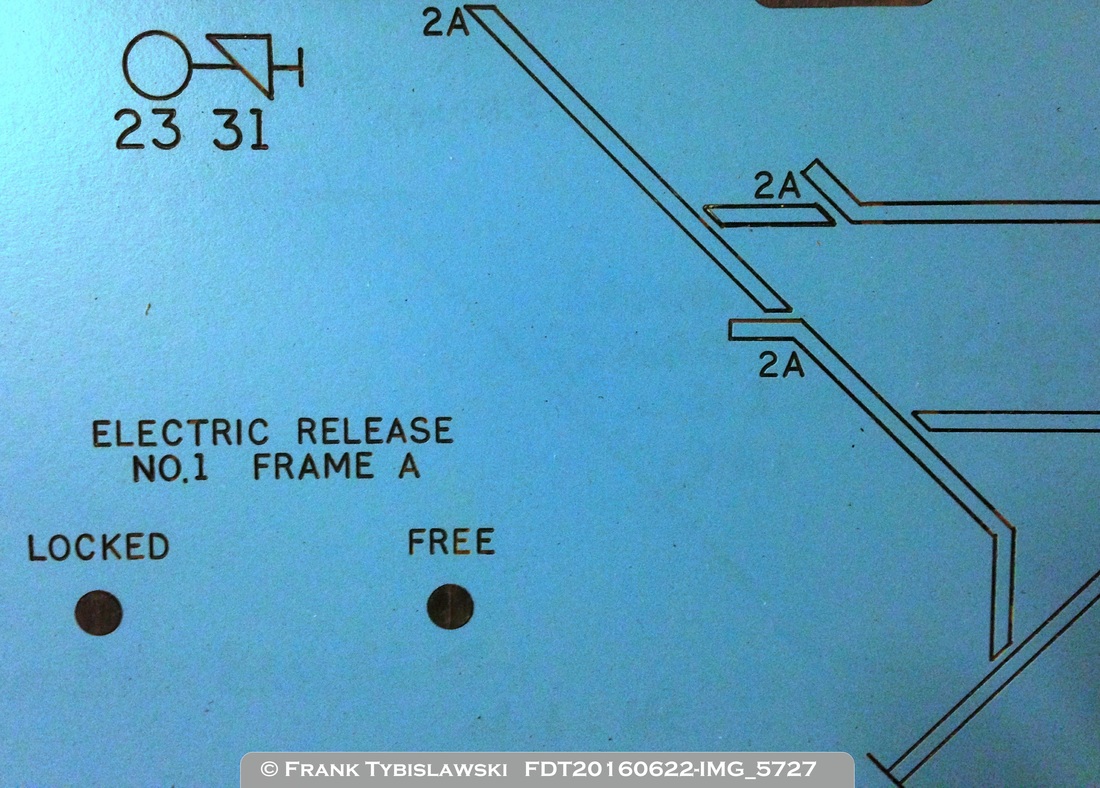
The metal framework was lightly sanded all over to provide a rough surface for new paint to stick to, and areas where the paint was damaged (scratched) were sanded so a smoother finish would result. The paint used was a Dulux Metalshield Hammered Finish (silver) in a spray can. The colour selected was a reasonable match as there were only three choices to choose from. To get the best finish each side was painted with it laying horizontal which seems to work better with this special kind of paint. The new colour is more grey-ish than the original but looks very fresh. The photo below shows the bare metal framework fully repainted and ready to have the other pieces re-attached.
|
I also experimented with the different lamps and LED's I had available. My first choice was actually a 17 volt lamp from some old telecommunications equipment. My reason for trying this is that I only have a limited number of 12 volt lamps and LED's and I want to keep them if possible for another (larger) panel restoration project which will follow this project. The 17 volt lamps when powered up from the 12 volt supply still give a good light - and I have no other use for them at this stage.
I tested all the connections from the terminal strip to the lamps and repaired two connections where the wires were broken. With that done I was able to identify which wire went to each lamp. I also tested the bells but neither seemed to work on 12 volts. The terminal strip connections I was able to identify were as follows:-
|
