Bundamba Panel Project: This is my biggest and most complex project ever and isn't a restoration project, but a full construction project. The original Bundamba panel is still owned by Queensland Rail although the panel, like others on the Ipswich line, have all been out of use for many years. The objective of this project is to build an almost full-size replica control panel and make it fully operational and able to simulate multiple train movements to realistic period timetables.
Panel Description and history.
The local control panel at Bundamba station was installed in 1980 and was commissioned on the 23rd and 24th of August 1980 when the mechanically interlocked signal cabin and semaphore signals were replaced with three-aspect colour light signalling in preparation for electrification between Darra and Ipswich. The panel at Bundamba was installed in the station office on the Up platform which allowed the old signal cabin on the Down platform to be demolished.
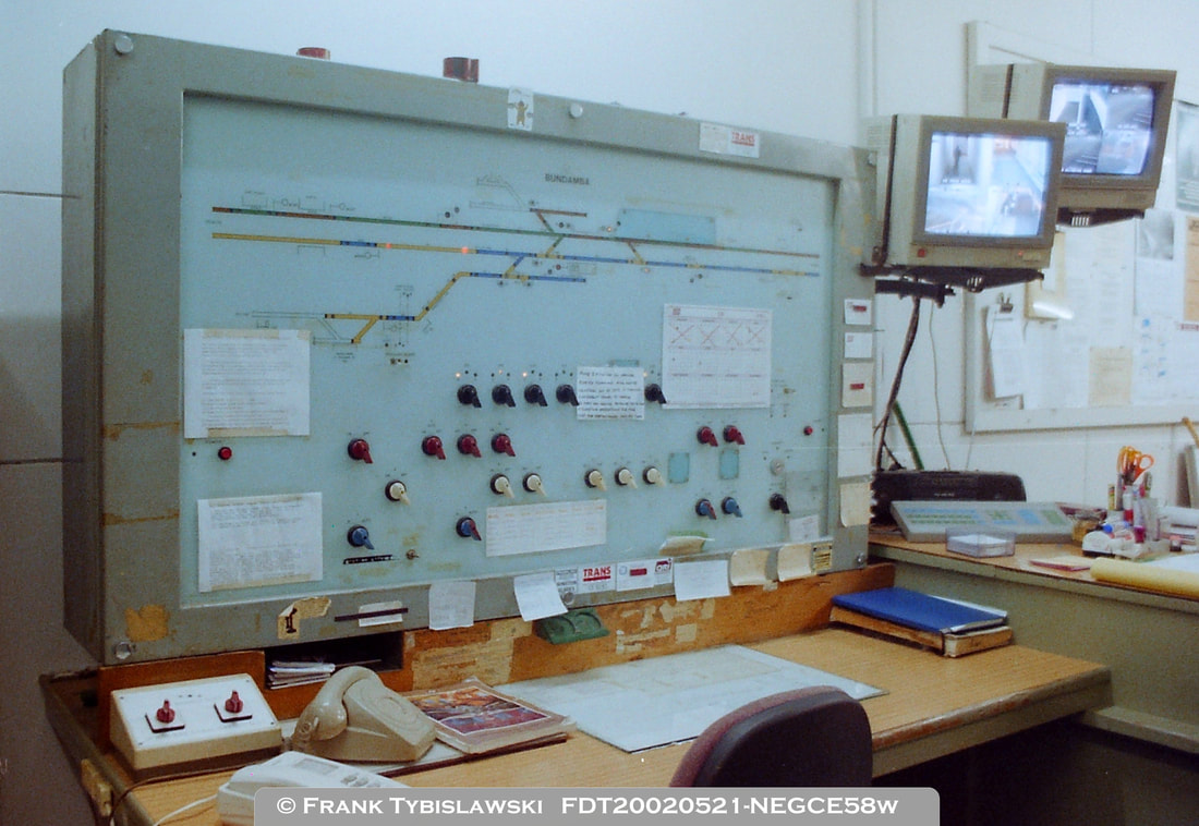
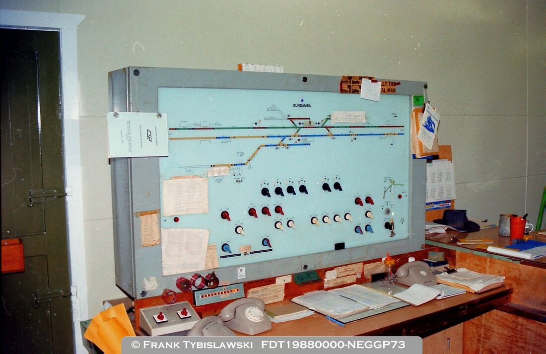
The panel is a large floor-mounted vertical panel which had a timber desk built in front of it. Although it can not be seen in the adjacent photo the panel sits on a sturdy metal post which also protects the cables between the relay room and the panel. The track circuit and signal indications utilise incandescent lamps, and two-position rotary switches control the points and signals. The black switches (originally 6 of them) controlled the points and catch points, the red switches (6 of them) controlled the colour light running signals, the white switches (originally 8 of them) controlled the position light shunt signals, and the blue switches (4 of them) allowed the selected main line running signals to be placed into Automatic operation. When originally installed the panel was either used in Automatic or Local control only, Remote operation was not possible at that stage. Automatic working allowed trains to run through on the Up line and Down line without the Station Masters involvement. Local working was used when movements other than strict Up and Down through trains were required, i.e., terminating trains, branch trains or shunting trains. |
On the 21st of March 1984 the signalling at Bundamba was altered to allow Remote Control from the Mayne Control Centre, the local panel could be cut-in if required. It appears that when trains ran on the Swanbank Branch Bundamba needed to be attended, and the panel was placed into Local Control. It was not until a year later, on the 24th of April 1985, that further signalling alterations were made to allow trains to and from the Swanbank Branch to run when Bundamba was unattended. This signalling alteration required the installation of key-switches mounted near signal BA4 for use by train crew, and additional switches in the station office.
The image above shows the panel in 2002 by which time a few modifications had already been completed. The Down siding at the Dinmore end had been removed with the siding, points switch and signal switches all covered over with coloured plastic pieces. The additional switches provided in 1985 can be seen to the bottom left of the main panel. A small additional toggle switch was also provided to connect the Swanbank Branch telephone circuit to Mayne Control Centre. |
panel layout.
|
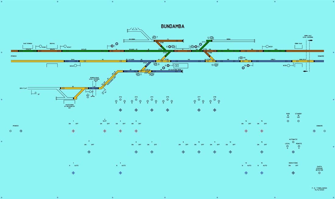
The image below shows the final version of my working diagram for the panel layout. This has been redrawn with LibreCAD using images available at the time. Just for the record the diagram is 1164 mm by 692 mm.
|
The trains.The intention is to have the panel built to show it in 'as new' condition and simulate the working of trains that were operating at that time in the early to mid-1980's. The following train types that existed as briefly described below:-
If a more modern era is considered, coal trains bringing coal from Macalister or Jondaryan to Swanbank could be simulated. This would include the operation of additional light engines which ran from Ipswich to attach to the rear of the consist to haul the train to Swanbank. These trains also operated while export coal trains operated in their final years.
|
In examining the types of trains and the lengths of the various track circuits, it was necessary to understand the physical length of each type of train, as well as the track circuit detection length of each train type. Consider for example a standard 3-car EMU - the first axle and last axle (which is what actually operates the track circuits) are further back under the carriage compared to the actual end of the carriage at the coupler. The following calculations were made to show as accurately as possible where the axles of each train type would be which was then compared to track circuit lengths while programming the Arduino for the panel operation.
|
signalled routes.Contrary to popular belief, there were a limited number of possible train/shunting movements possible at Bundamba. The signalling was designed to accommodate train movements at the time without extravagant expense in catering for every possible scenario. The following moves were not possible:-
|
The following moves were possible and I would have witnessed most if not all of these occur at some stage:-
|
considerations.
The exact dimensions of Bundamba panel are unknown, the replica panel will be of a similar size but slightly smaller to make it easier to move. The Bundamba panel is also of a very heavy steel construction which is impractical to replicate, the replica panel will have a lighter timber framework painted a similar colour.
Bundamba panel uses incandescent lamps however the replica will use LED's for improved reliability, lower power consumption, and simplified wiring. |
The switches used on Bundamba Panel are made by Kraus Naimer and unfortunately are fairly expensive. An approximate cost of $70 per switch equates to a cost of $1750; an alternative design of switch was used however the same Kraus/Naimer switch handles (knobs) will be used with custom made fittings to match the two different brands.
The programming will need to be quite specific and complicated to replicate the correct operation of the panel. Some features to include are as follows:-
|
PRE-construction.Construction of the panel was always planned to be a slow a careful process with development of the hardware happening in parallel with development of the software. It was also deemed necessary to make some prototypes of various elements to test the concepts before committing to the final big build.
The first major test was to have a small section of the panel printed and drilled to test a number of design features; check accuracy and alignment, check colours selected, test hardware mounting techniques, and allow some further software testing. The results were very promising and indicated that only a few minor design changes to the CAD drawing were needed. Even this first attempt of small section produced a very professional result as shown below. 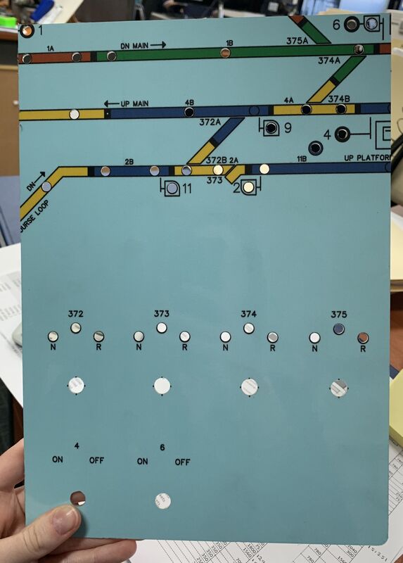
A second item to test the software running on the Arduino was the construction of a temporary switch panel with the 24 point and signal switches installed.
This enabled testing of the software with actual switch inputs, and testing features of the software which had not been able to be tested before. Software features tested were signal timeouts, signals working in 'auto' mode, route locking and approach locking. 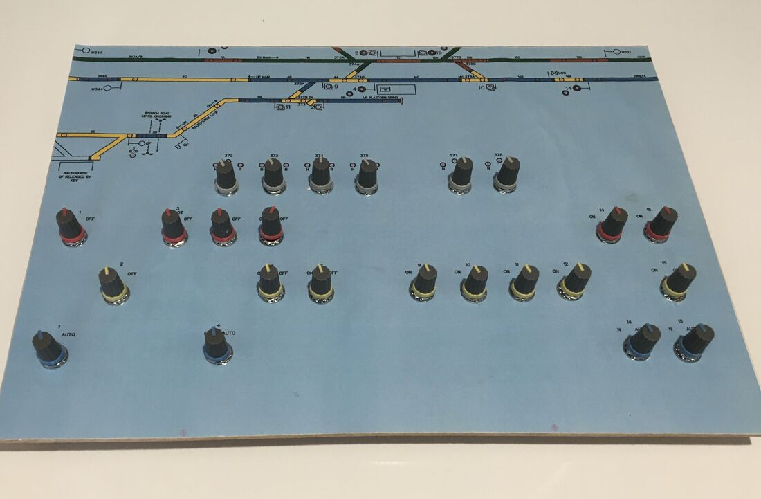
|
Parts & Costs.
Below is a list of most of the parts required and their associated costs. Also included are some general or specialist tools that were needed.
|
CONSTRUCTION.Part 1
The first part of the panel construction was to have the panel fascia printed on aluminium and to drill out the holes for the switches and indications. The sign company could not achieve the accuracy required for the hole drilling however the sharpness, colour and quality of the print was first class. Thanks to everyone at Artcraft at Sumner Park in Brisbane for their assistance. After receiving the fascia there were 129 holes to be drilled in total. 25 are for rotary switches, 1 is for the keyswitch, 2 are for the Block Bell push buttons and 101 are for indications. Of these the 101 holes for indications had to be super accurate and were tackled last so experience drilling the less-accurate switch holes could be gained. Working on a previous sample piece of the panel I discovered the best process was to center punch each hole, drill a small pilot hole, drill out with larger drill bits as big as was deemed safe. Then file out the holes to just under the required size. At this point it the hole was off centre the filing could correct that. A final drill of the finished size to ensure roundness. A fine round file removed any burs to give a clean finish. The image below shows the holes for the 25 rotary switches and two push buttons completed. Also on the left one of the red push buttons is test fitted. 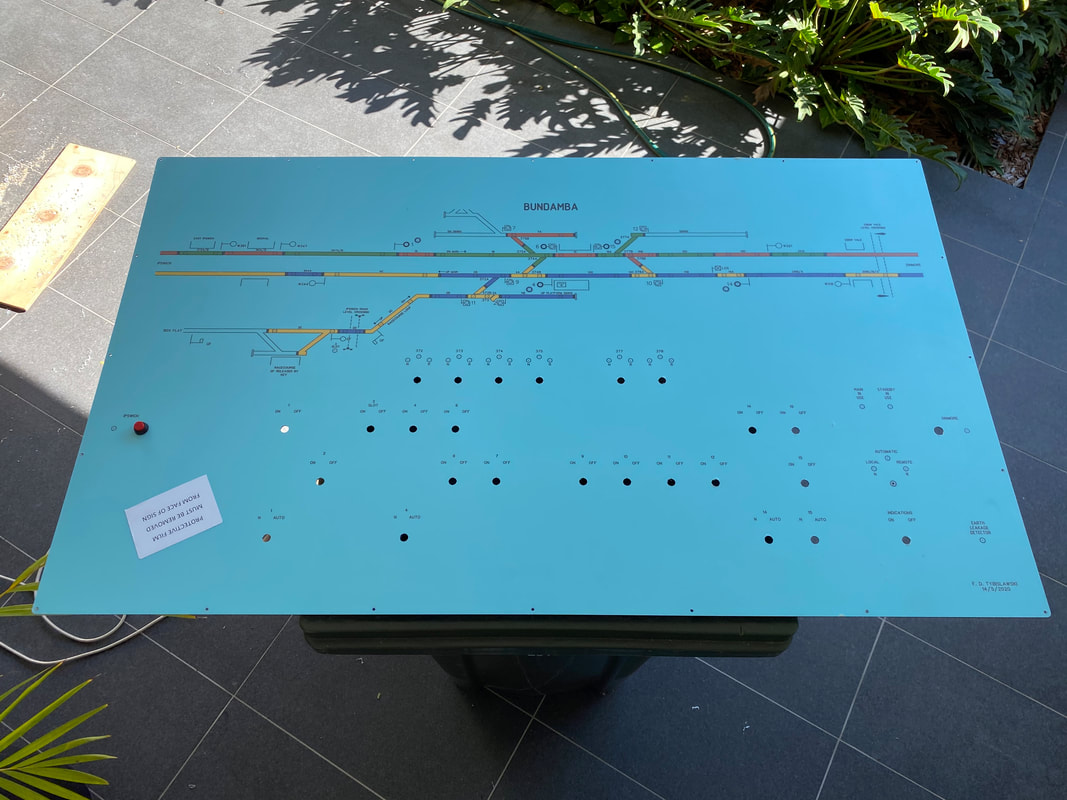
|
Next to be fitted was the keyswitch which required an unusually shaped hole, basically a larger diameter hole with flat sides which prevents the keyswitch itself turning when the key is turned. The same process was used but with more filing to get the required shape.
The image below shows the keyswitch fitted. The exact type of switch used on the original Bundamba panel is unknown but a very similar look was achieved with a modern equivalent with the addition of a large grey washer . 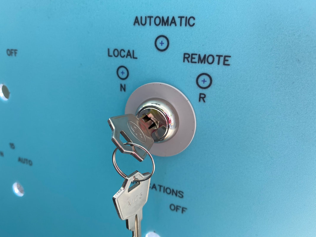
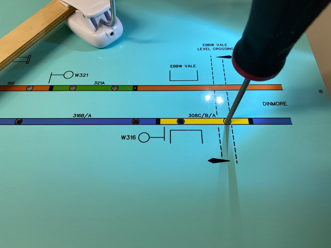
The final stage was to carefully drill and enlarge the 101 holes for the indications. The same process was applied starting with a small hole which was then carefully re-drilled and filed out to 5mm diameter. Once in a rhythm the process was quickly completed in a few hours. The image below shows the last hole about to be carefully filed out to 5mm. The file used is a round 4mm chainsaw file..!!
|
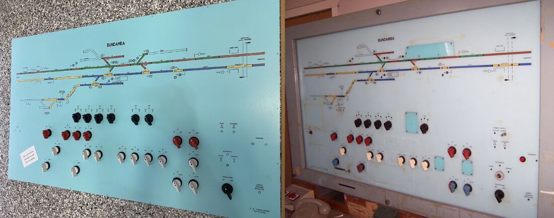
The image below shows a quick comparison photo with the original Bundamba panel. The switch knobs were temporarily placed in position to see the overall effect that will be achieved.
- - - - - - - - - - - - - - - - - - - - - - - - - - - - - - - - - - - - - - - - - - - - - - - - - - - - - - - - - - - - - - - - - - - - - - - - - - - - - - - - - - - - - - - - - - - - - - - -
|
Part 2
The next task was to make a relatively lightweight timber frame to support the fascia. The timber frame has a layer of thin plywood added which is needed to secure the 25 rotary switches. These switches have small lugs to prevent the entire switch turning with the lugs set into the layer of thin plywood. The plywood added some strength to the panel and additional section of thicker plywood were added to mount the LED's. The timber framework would also support the wiring between components and the Arduino, and has two extra horizontal timbers for that purpose. The image below shows the timber framework only before the thin plywood layer was added. 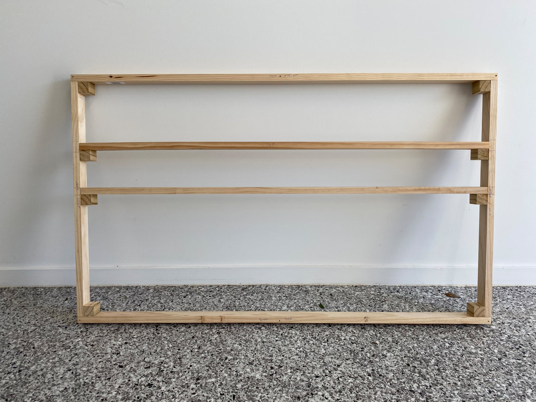
|
After adding the plywood layer the holes of all sizes had to be re-drilled using the aluminium fascia as a template. The layers were screwed together and into the timber framework to hold everything in place.
Again some filing (do you file wood?) was needed to obtain a neat edge around the holes in the wood. A series of screws around the perimeter keeps all the layers together and sturdy. 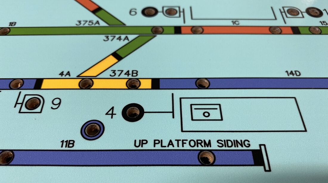
|
- - - - - - - - - - - - - - - - - - - - - - - - - - - - - - - - - - - - - - - - - - - - - - - - - - - - - - - - - - - - - - - - - - - - - - - - - - - - - - - - - - - - - - - - - - - - - - - -
|
Part 3
The next part of the construction process was to begin to add some of the electronics. A small plywood panel was added to mount the Aurduino Mega into the frame but other components are mounted to the timber frame as shown above. On the side of the frame are the power control relays as well as the socket for the external control box. Below the timber frame is the Arduino Mega with a screw shield for easy and reliable connections, and also to enable the Arduino Mega to be easily replaced in the event of failure. Above the timber frame is a small screw terminal strip which is the I2C bus and two of the I/O expansion cards are also visible. 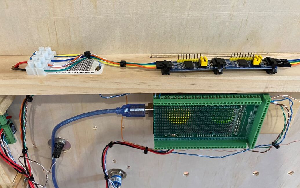
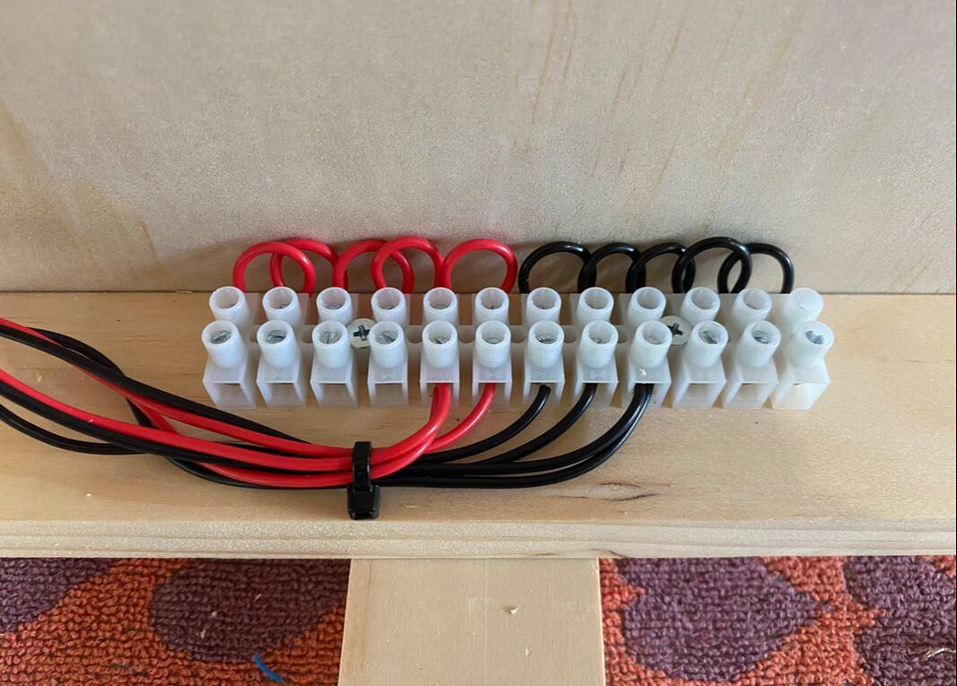
The photo below shows the beginnings of the +5 volts and 0 volts wiring with a terminal strip divided in half for each. Another common point for a switched +5 volts supply was also needed to cater for the Indications switch which is immediately below the key switch. The Indications switch allowed the panel operator to turn off all the indication when the station was unattended to conserve the life of the incandescent bulbs in the real panel. While the replica panel utilises LED the feature will still work the same and allow the panel operator to turn off the LED's while still having all functions of the panel running.
The control box is not part of the original panel but was felt as necessary to have. The control box, which can be unplugged at any time, removed the need to have a power switch on the panel and allowed for extra functions to be used during testing and operation.
|
When the panel is connected to the 5 volt power supply nothing will happen unless the control box is connected and the red button pressed. This connects the 5 volts internally and the Arduino program will start running. The control box can be unplugged and the panel will keep running until the 5 volt supply is turned off or the control box is reconnected and the black button is pressed.
The yellow button is connected to the Arduino Reset pin which, when the button is pressed, causes the Arduino program to restart - this is a useful feature during testing to easily and quickly restart the Arduino program. The two black push buttons are connected to Arduino input pins and have no function at present. It is planned that these may be used in the future to allow trains to pass signals at 'stop' if Single Line Working is added to the program. The two toggle switches also have no function but are connected to two more Arduino input pins. The switches are Momentary-Off-On in configuration to allow for a momentary or permanent input to be selected. Only one switch is presently used and switching the switch on enables the Arduino to output serial data to the computer (when connected) for diagnostic purposes. The serial data output is normally disabled as it slows the programs operational cycles too much. 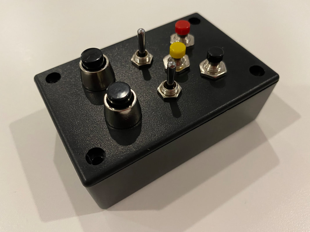
The other external feature of the panel is the small LED clock module which again is not a feature of the real Bundamba panel. It was necessary to have a clock showing the simulation time as it may be considerably different to the real time, and also allows the operator to walk away for hours and return knowing exactly what time the simulation is up to. The clock module also incorporates the Block Bell buzzer which enables the sounds to be emitted from the front of the panel close to the operator.
|
- - - - - - - - - - - - - - - - - - - - - - - - - - - - - - - - - - - - - - - - - - - - - - - - - - - - - - - - - - - - - - - - - - - - - - - - - - - - - - - - - - - - - - - - - - - - - - - -
|
Part 4
After installing the basic wiring for power and the I2C bus it was time to start installing some of the 101 indication LED's. The first ones installed were all the white LED's in the lower part of the panel. There are 26 in this area with most of them being the points indications and others for Block Bell indications, keyswitch indications, power indications and the Earth Leakage indication. Behind each area a section of plywood was added and then drilled at 5mm from the front of the panel. Into each hole a 2cm long section of 5mm diameter acrylic rod was added to act as a light guide. Behind the light guide was placed a white LED and both were held together with 6mm glued heat shrink. Adjacent the Arduino a resistor board was added with 26 resistors (3K6 ohms) to limit the LED current. Each LED was wired from the Arduino output via the resistor board to one of the white LED's. |
programming.Prior to construction of the panel, time spent waiting on parts from the USA and China allowed a lot of programming to take place. The Arduino Mega is the basis with expansion boards required to cater for the large number of inputs and outputs required.
A large number of variables are required to allow the panel to operate and display like the real one. Some variables required so far include:-
|
Signals
Each signal, and each signal route if multiple routes exist, has a small sub-section in the program to determine if the signal is able to be cleared to a 'proceed' aspect when the switch is placed in the 'off' position. If the signal is operating in the 'Auto' mode, the signal will clear to a 'proceed' aspect again once the previous train has cleared the signal in advance. Program sub-sections also exist to determine if a signal overlap is active beyond a 'stop' signal, or if a signal switch has been restored to 'on' and a signal timeout is in progress. The overlap and timeouts maintain the integrity of the route until any trains potentially approaching the signal have been proved to have stopped. Points Each set of points has a small sub-section to determine if the points are 'free' or 'locked', and if 'free' can they be moved from Normal to Reverse or Reverse to Normal. Points involved in a signal overlap, or with a signal cleared over them are locked in position and cannot be moved. Where one half of a crossover becomes 'free' after the passage of a train, the program checks the status of the other half of the crossover before allowing the 'free' light to be lit and/or allowing the points to be manipulated. A small random time variation is built into the program to accurately simulates the mechanical variations in the time taken for points to move. Trains Larger sections of the program are devoted to simulating the movement of trains. Different sub-sections exist for each train type allowing each train type to have different sectional running times and different routing characteristics. The routing characteristics ensure an electric train will not run onto an un-electrified track even if the panel operator signals it in that direction. This effectively simulates a driver challenging an incorrectly set route. |
Timetables.
While developing the program for the Arduino several train types were used to test various scenarios. It became apparent that the simulated panel operation would need several different timetables to cover all the train types it was desired to operate. There would also need to be a simple method available to allow the panel operator to chose the desired timetable, and the desired simulation start time.
The method used to select the desired timetable and start time is as follows.
|
Working Timetable - 8th June 1980
The new signalling at Bundamba and the local control panel were brought into operation on the 23rd and 24th of August 1980. This was less than one month before the commissioning of electric train services between Darra and Ipswich on the 20th of September 1980. The Working Timetable dated the 8th of June 1980 would have still been in force when the panel was commissioned in August 1980. At this time EMU's were only running from Ferny Grove to Darra with connecting railmotors or diesel hauled trains running to Ipswich. Some services during peak times were also worked by railmotors or diesel hauled trains between Ipswich to Brisbane. Trains running on the Swanbank branch were shunt trains to the fertiliser siding between Bundamba and Box Flat, and race trains to Bundamba Racecourse. Other through traffic on the main line consisted of livestock, fuel, wheat and general freight services, and long distance railmotors and passenger trains. The finalised timetable for the replica panel is based on a Wednesday when most trains were running with an additional train added to enhance the operating experience. |
prototype photo's & data:
trains & signals.
|
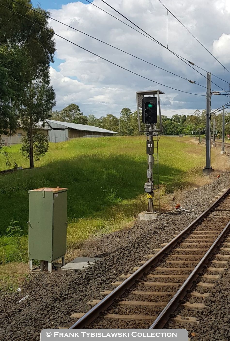
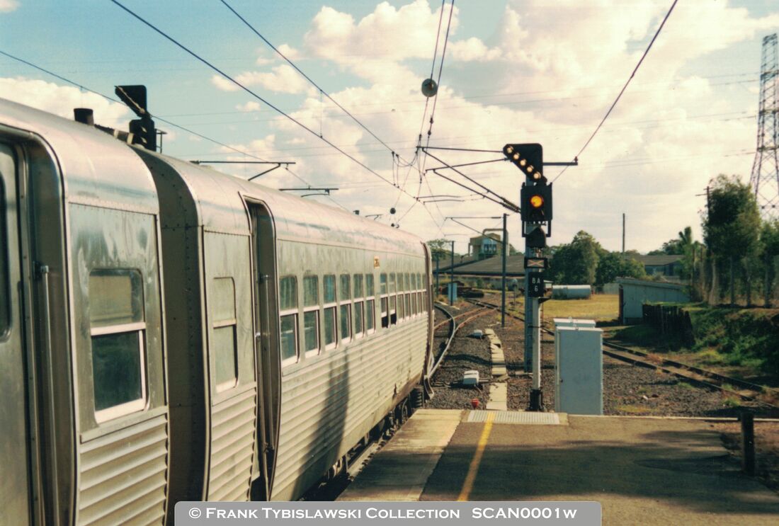
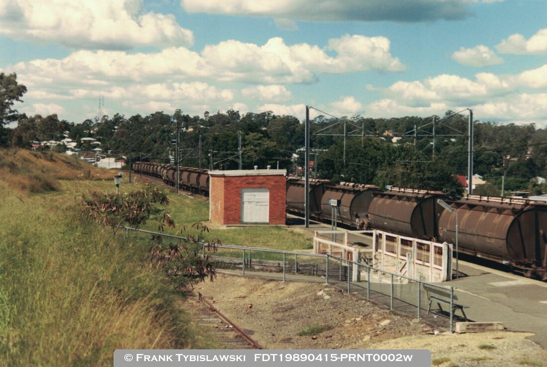
Right: The only image I have found of signal BA1 at the Ipswich end of Bundamba on the Down Road. It was and still is a quite standard three-aspect colour light signal, with incandescent lamps in a DML manufactured signal head, on a straight galvanised steel post.
The telephone at the bottom of the post is original from the day of commissioning. Initially these were connected to the phones in Bundamba station (SPT - Signal Post Telephone) but were later re-wired to connect to Mayne. The small box above that was for the emergency push buttons used if the remote control of the signalling from Mayne was disrupted. The former Rothmans Tobacco Factory can be seen to the left and the grass now covers the site of the three sidings, one into the factory, a second to form a long run-round loop, and a third long dead-end siding - very much as shown on the panel diagram. |
|
|
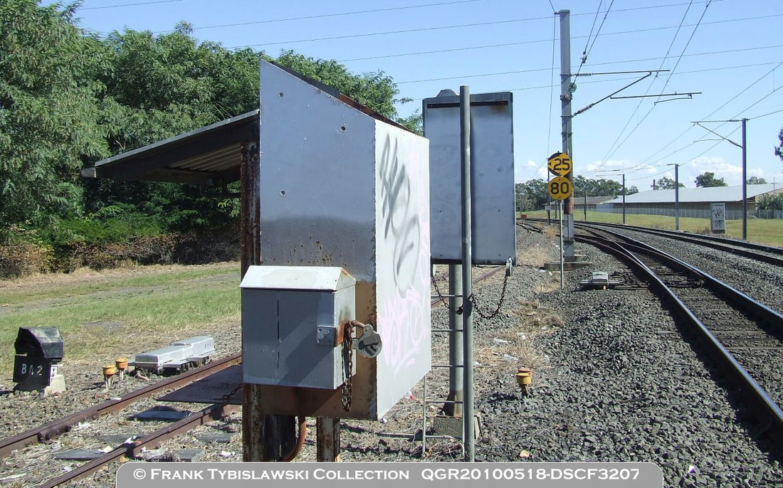
Right: The only image I have found of signal BA2 at Bundamba. It protects the catch points and controls trains shunting from the Up Platform Siding or departing from the siding to Bundamba Racecourse. No.373 points machine is just beyond signal BA2. Near the centre of the image, attached to the Ordinary Staff throw-in box, are the key-switches allowing train crew to clear signals BA4 or BA6 to the Swanbank Branch when Bundamba is unattended. These key-switches were commissioned on the 22nd of April 1985.
|
|
Above: Signal BA3 at Bundamba Racecourse as I first saw it had a lattice post and a smaller two-aspect signal head. This was later replaced with a conventional round steel post and two-aspect signal head as shown at right.
|
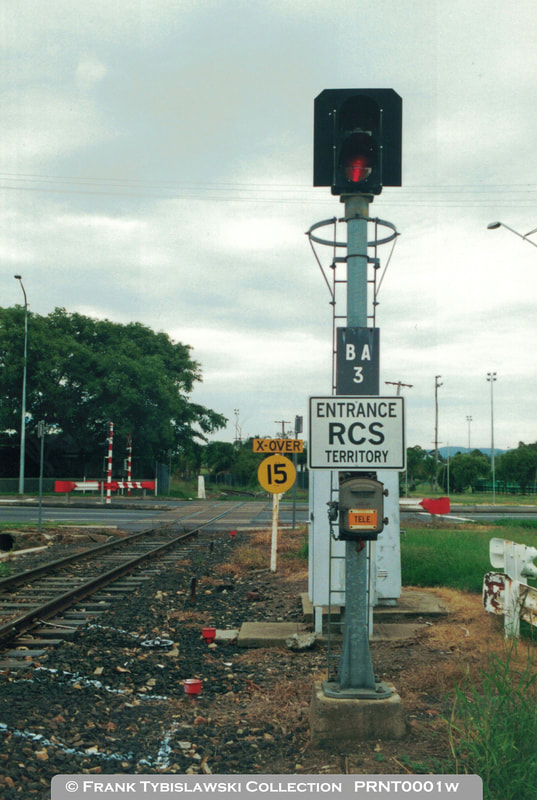
Above: A more modern view of signal BA3 at Bundamba Racecourse after the new signal post and head had been fitted. The 'ENTRANCE RCS TERRITORY' sign was fitted on the 15th of February 1999. The signal has since had Super Control added as further protection for the level crossing.
|
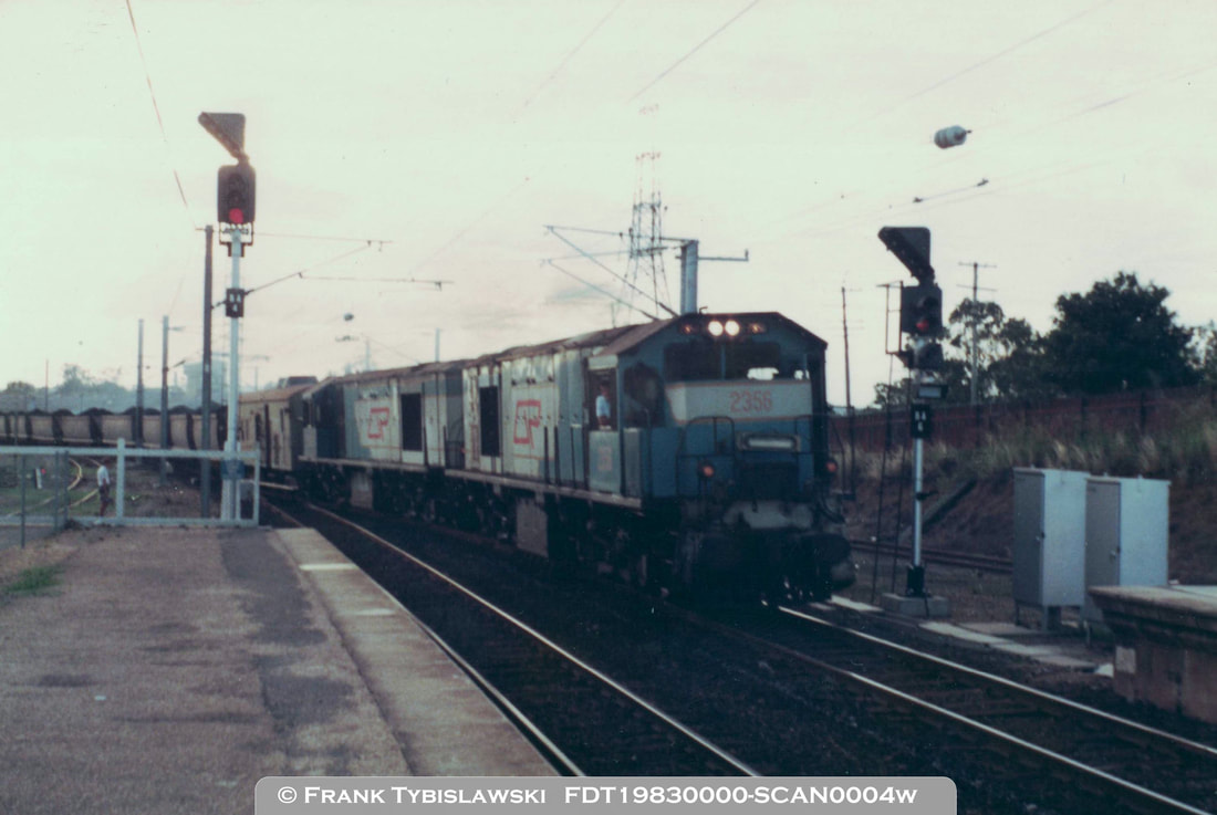
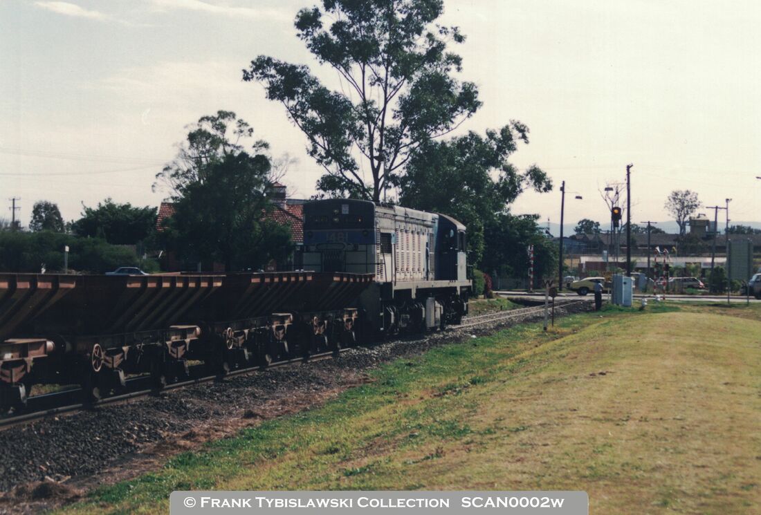
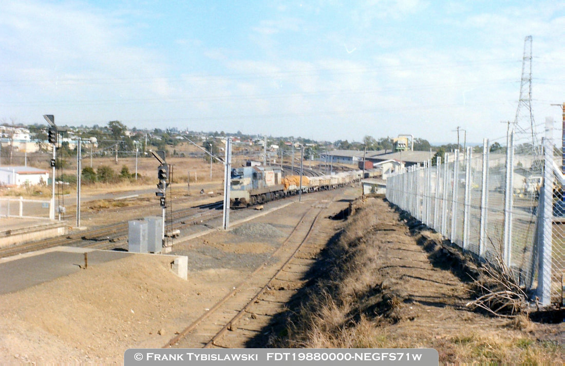
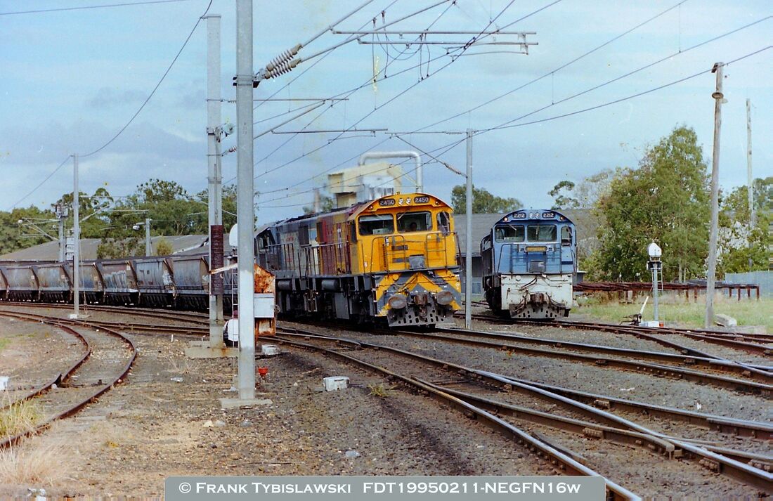
Above: An early view of Bundamba looking towards Ipswich with a loaded coal train (34 VAO with 2 TGV's) leaving the branch and crossing over via No.372 & No.374 crossovers to the Down Road. Signals BA4 and BA6 at 'stop'. Signal BA14 also protects this movement as the overlap beyond BA4 is unavailable so BA14 would also be held at 'stop' and would not clear even if you did operate the switch on the panel.
Above: Signal BA4 cleared towards Ipswich (green aspect) and a Camp Wagon in the Up Platform Siding, probably placed there by a local shunt train. A typical export wheat train of the period passing through on the Down Road.
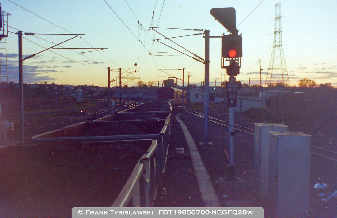
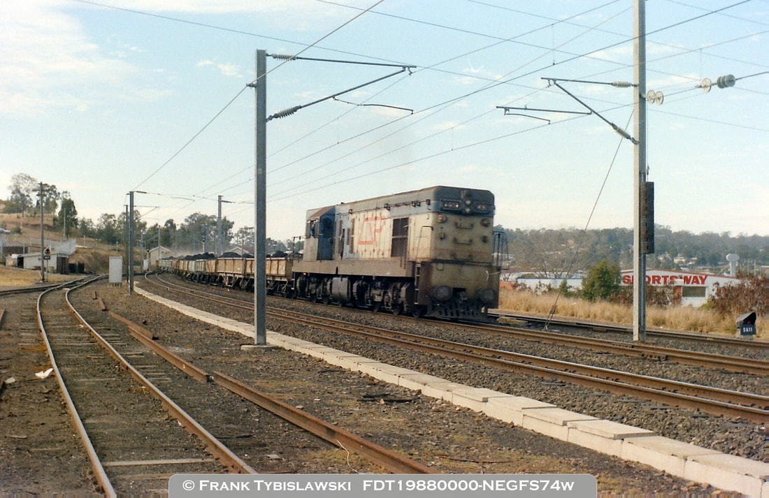
Above: Signal BA6 in the foreground and behind a reminder that things do not always go to plan. The van on the spoil train has derailed departing the Down Sidings late one winters afternoon. Derailments will not be simulated on the replica panel..!!
Above: Signal BA6 cleared towards the Swanbank Branch for a Bundamba to Bundamba Racecourse railmotor to depart. Note that BA6 only displayed a yellow aspect due to the low speed crossovers. The white cross above the number plate indicating an un-wired route has been signalled, the same indicator would be lit for a shunt move into the Down Sidings through No.375 crossover which can be seen to the right of the railmotor.
|
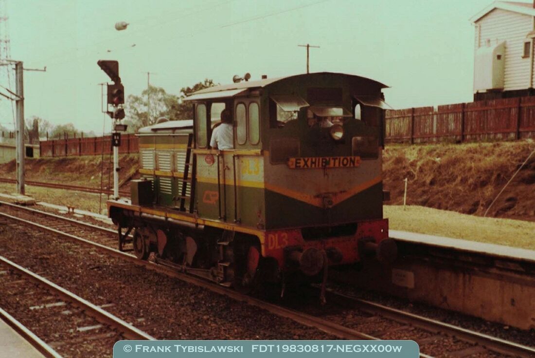
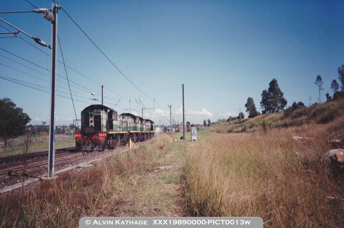
Above: An early view of Bundamba with signal BA6 in view. Locomotive DL3 has just detached from an excursion train and is waiting for signal BA6 to be cleared via No.374 crossover to Ipswich. It will display a steady yellow aspect for this route.
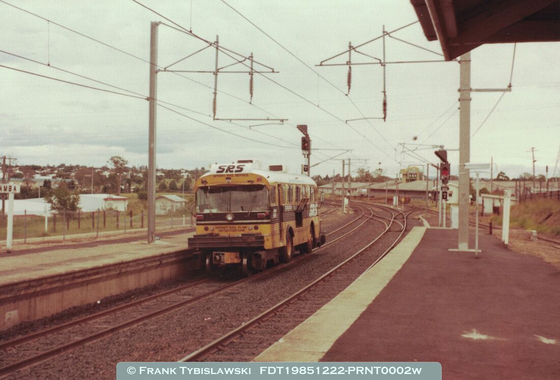
Above: An early view of signals BA4 and BA6 with BA4 cleared to the Branch (yellow aspect with Junction Indicator lit) for the Sperry Car to do some track testing.
Above: Signals BA4 and BA6 in the foreground, and to the right of the loco you can just see the back of signal BA7 which controlled exit from the sidings to either the head-shunt or the Down Road. The train is actually running Wrong Road to Ipswich due to Single Line Working - hence signal BA6 would have been at 'red' as it can not be cleared to the Wrong Road. Chances are the local panel was actually cut-in on this day due to the track closures. Wrong Road running will not be simulated on the replica signal panel at this stage however provisions have been made for it to be simulated in the future.
Above: Another early view of Bundamba from 1988 with a spoil train from Swanbank pushing back into the Down Sidings to re-marshal the train. The Shunt signal on BA6 and the white cross (un-wired route indicator) would have been lit to perform this movement.
|
|
Right: Although very small, post mounted signal BA7 which controlled the movements of trains either towards the dead-end behind the Down Platform, or exiting to the Down Platform is visible to the left of the silver box to the left of the train. Signal BA11 is just in view at the far right of the image.
Below: Also very small, but one of the white lights of signal BA7 can be seen to the right of the loco, above the second wagon, as the train pushes back onto the Down Platform, having just run-round within the Down Sidings. 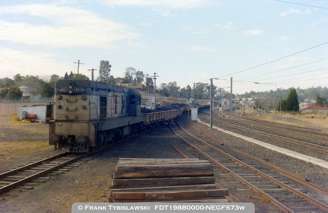
|
Note: This train was too long to fit between the signals on the Down Platform to run the loco around and place the Guards van at the end of the train for its trip to Ipswich. The Down Sidings and the Tobacco Siding was often used to shunt longer trains and those with only one Guards van.
|
|
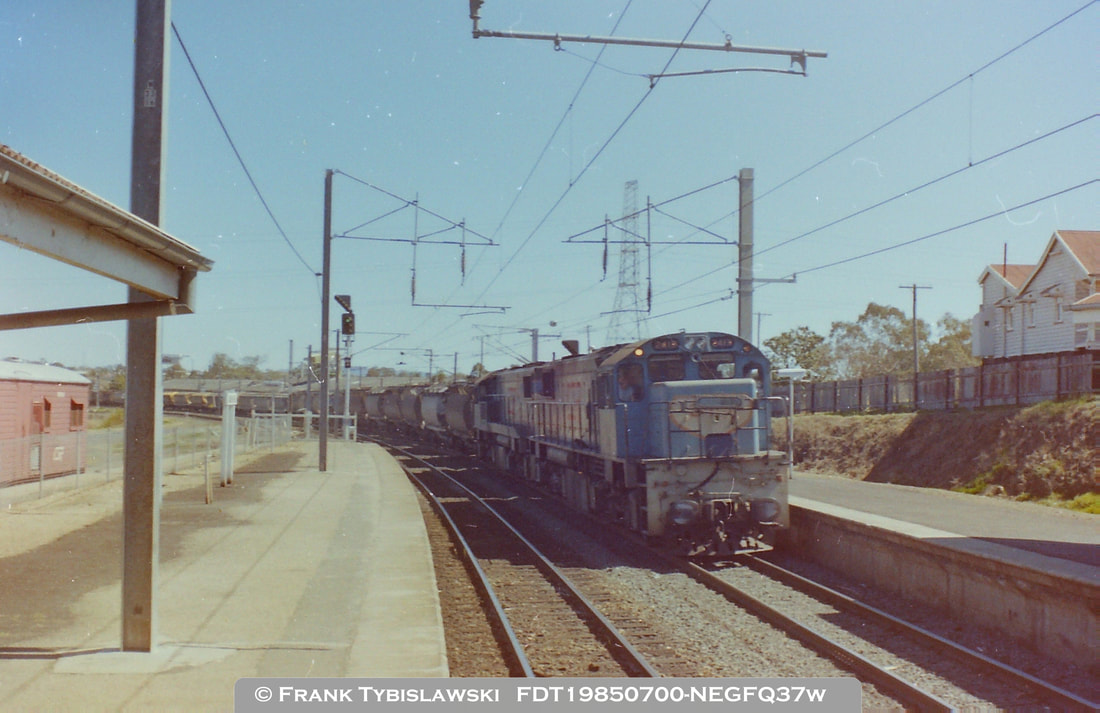
Left: Macalister to Swanbank coal train operation. The two assisting engines have arrived from Ipswich into the Down Platform and are setting back past signal BA6 into the Down Sidings. The Shunt signal on BA6 can just be seen to be illuminated in the photo and the un-wired route indicator (white cross) is also illuminated. These two locomotives will attach to the rear of the loaded coal train and haul the train to Swanbank for unloading; then after trailing back to Bundamba they will haul the empty train back to Macalister for re-loading.
|
|
Right: The loaded coal train from Macalister arrives at Bundamba and will stop with the last wagon on the Down Platform near the station office. The assisting locomotives in the Down Sidings will be given a proceed aspect in Shunt signal BA7 to travel via No.375 crossover and attach to the rear of the train. After a brake test, the assisting locomotives will be given a proceed aspect in signal BA6 to travel via No.374 and 372 crossovers onto the Swanbank branch.
A later revision of the replica panel program may allow for this type of operation. |
|
Above: Another view of the Ordinary Staff throw-in box and key-switches. Also in view at the left is the back of signal BA9 which is mounted on a post. The number plate has been recycled from another signal or station with the number 3 visible upside down.
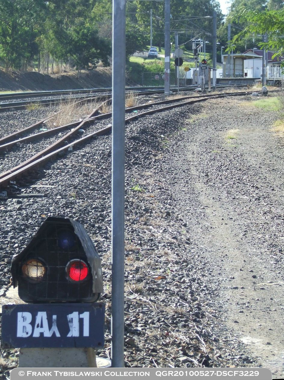
Right: Signal BA11 in the foreground, signal BA9 in the background, and to the right of signal BA9 is the back of signal BA3. The number plate on signal BA11 is another one recycled, this one appears to be from Kuraby and is also upside down.
|
|
|
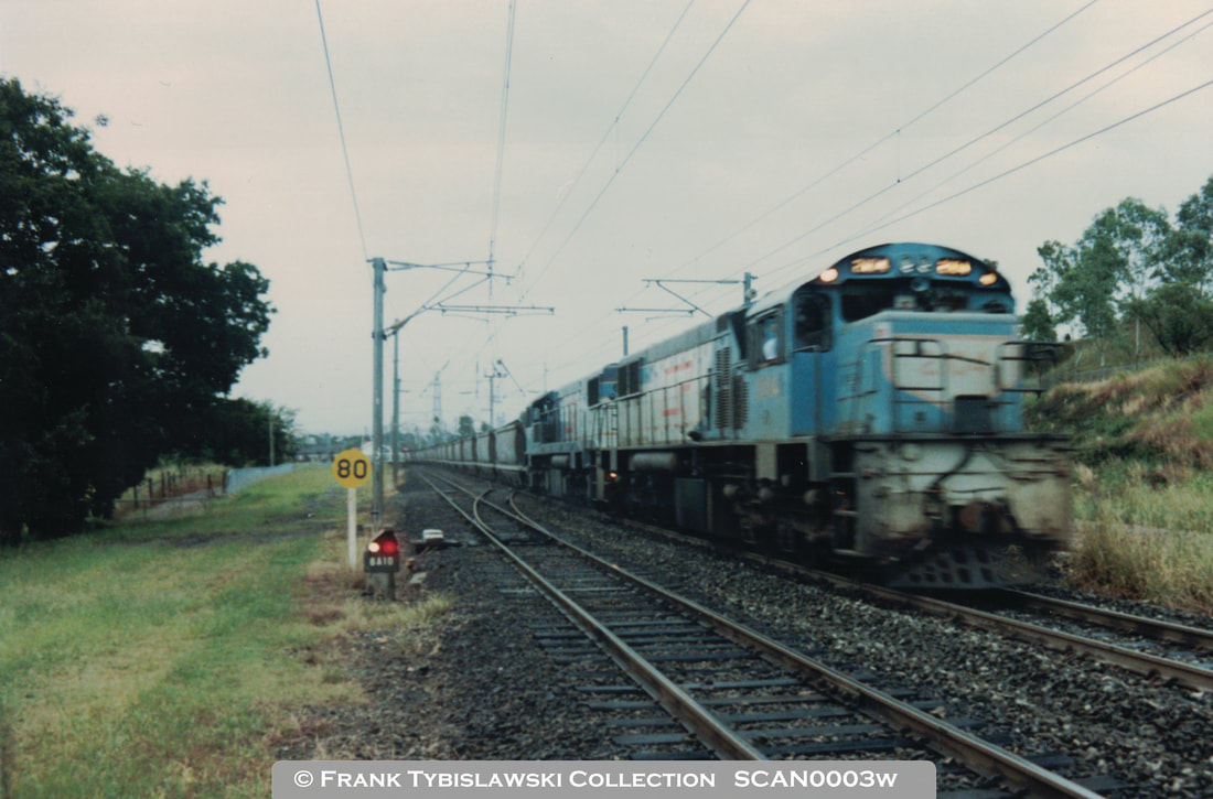
Above: The only photo I have found showing signal BA10 at Bundamba, adjacent to the Dinmore end of No.378 crossover. Signal BA10 was used for shunting movements (run-rounds) but is also cleared to a 'proceed' indication for trains travelling through on the Up Road between signals BA14 and BA4, or between BA14 and BA6.
|
|
Left: Not a lot to see here signal wise, but the grain train has crossed through No.378 crossover to the Down Road to go Wrong Road to Ipswich during Single Line Working. The relay-room is obvious in the foreground. While it would be very rare, it is possible to run an Up freight or grain train via the Down platform, perhaps passing a failed EMU in the Up platform. As mentioned elsewhere, Wrong Road running will not be simulated on the replica panel at this stage.
|
|
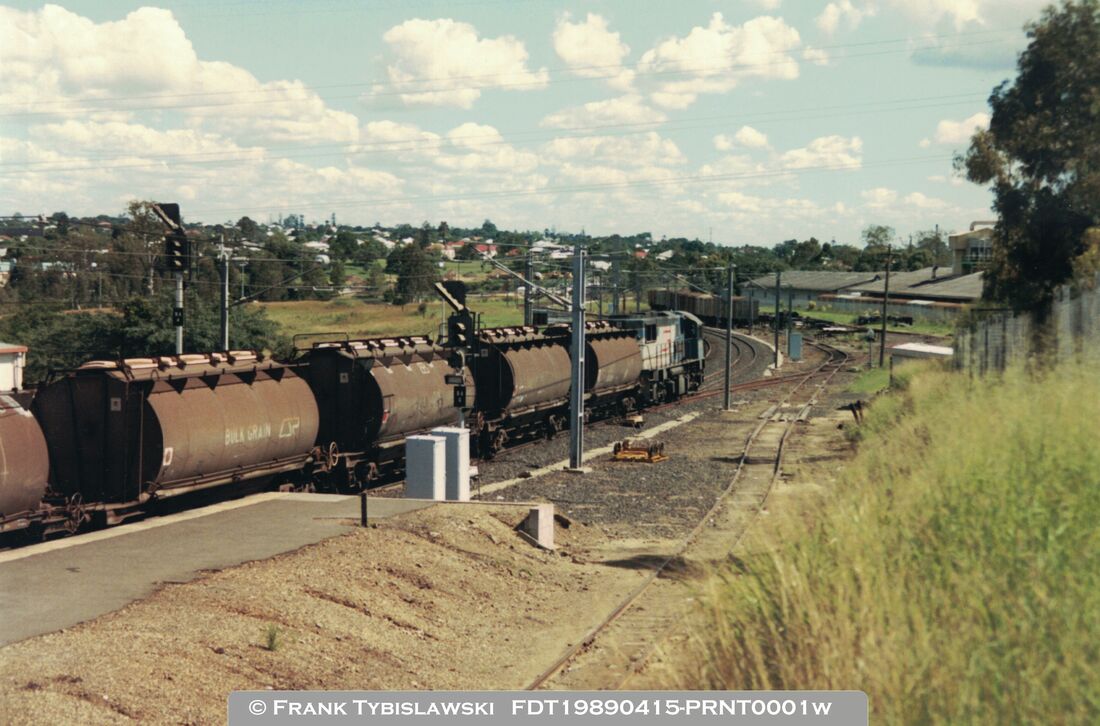
Right: Amongst the grass, between the far loco and the silver LOC relay cabinet, signal BA12 which controlled exit from the siding off the Down Road at the Brisbane end is visible. This siding was approximately 500m in length and was out of use by this time.
|
|
|
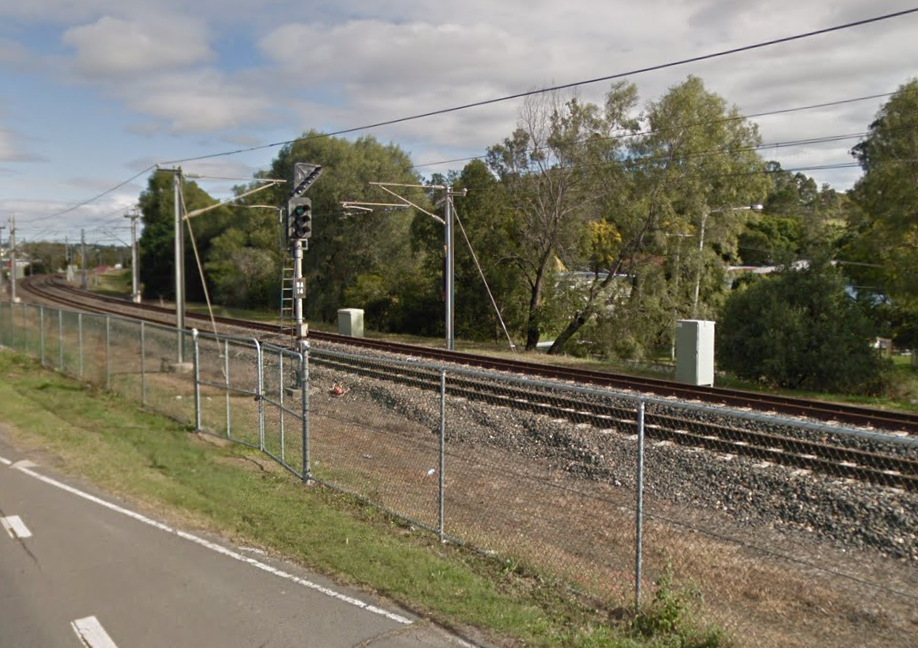
Right: A temporary image from Google Street View in 2017 showing signal BA14 adjacent to Brisbane Road on the Dinmore side of Bundamba. The junction indicator applies via No.378 crossover to the Down Road terminating at signal BA6 on the Ipswich end of the Down Platform. On the Up Road the signal applies to the Up Platform terminating at signal BA4.
BA14 was where Up trains were usually held when trains were coming off the branch. BA14 provided protection for the Station Master to stand on the Up Road to receive the Ordinary Staff from the train crossing from the Branch to the Down Road. |
|
|
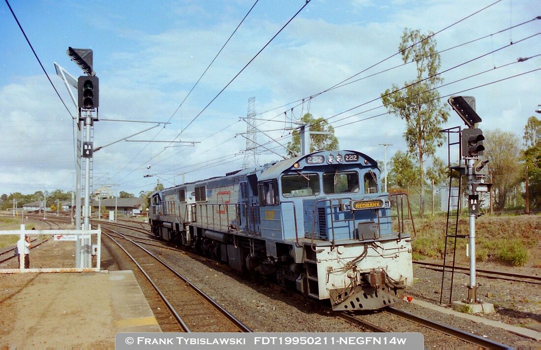
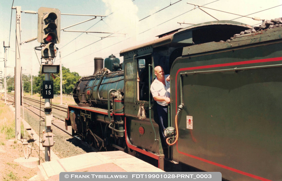
Right: Signal BA15 at the Brisbane end of the Down platform. BB18 1/4 1079 has just run-round a passenger train from Redbank and the loco is setting back onto the carriages. A 'proceed' aspect (green or yellow) in the main signal takes you towards Ebbw Vale on the Down Main Line. The position light Shunt signal could take you either in to the Down Siding via No.377 points which can be seen veering to the left, or via No.378 crossover to the Up Main Line as far as the Limit of Shunt board. When running into the siding the unwired route indication (white cross immediately above the number plate) was also lit.
|
|
prototype photo's & data:
|
|
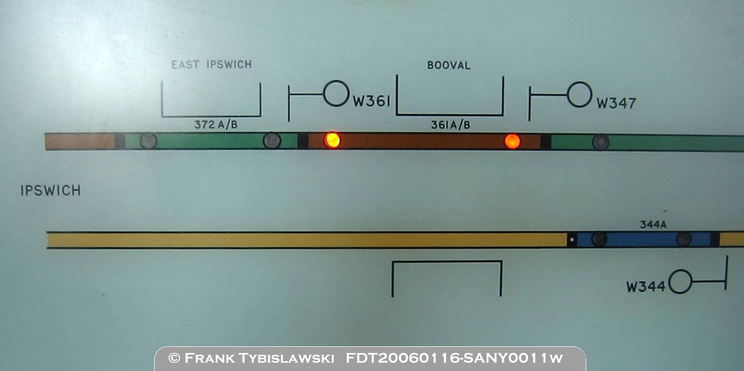
Above: The left hand edge of Bundamba panel shows East Ipswich and Booval stations. More detail is shown in the Down direction as this is the direction trains approach Bundamba from. Although only shown as one block on the panel, they each represent two track circuits as indicated by the 'A/B' designation. Signal W372 (not shown on the panel) was at approximately 37.2km from Roma Street or just east of Ipswich. Why the Down signal and corresponding track circuits carried an even number has never been established. Signals W361, W347 and W344 are indicated but not repeated. Track 361A/B is shown occupied by a Down train. Track 344A is shown as it is the overlap circuit for signal BA4 to clear to a yellow aspect - this is indicated by the small black dot.
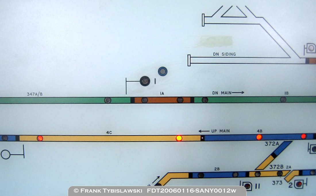
Above: Signal BA1 on the Down Main appears to show no light, and the 'Auto' indicator light also appears to have blown. With the panel not in use for controlling trains at this time panel bulb failures were often not repaired. Track 4B and 4C are shown as occupied by an Up train. The dead-end Down Siding was approximately 320m from clear of points to the stop blocks. The run-round within the tobacco factory siding was approximately 240m and the length within the factory gates was approximately 140m.
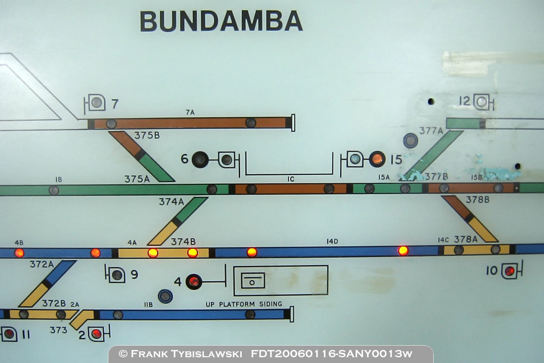
Above: The central part of the panel showing the Up and Down platforms, the four crossovers, the catch point from the Up Platform Siding and the Down Siding points and catch point. The headshunt behind the Down Platform, track circuit 7A was approximately 180m from BA7 to the stop blocks. The distance between signals BA6 and BA15, which limits the train length which can be run-round on the main line is approximately 169m.
A number of bulb failures are apparent in signals BA6, BA7, BA9 and BA11 which should all be showing a red indication, and BA15 and BA4 'Auto' indications which should be showing a white light. Signals BA2, BA4, BA10 and BA15 are all showing a red indication. Track 14D, 4A and 4B are all occupied by an Up train. The Up Platform also shows the symbol to represent the local panel and which way the panel operator faces (towards the Up Road). 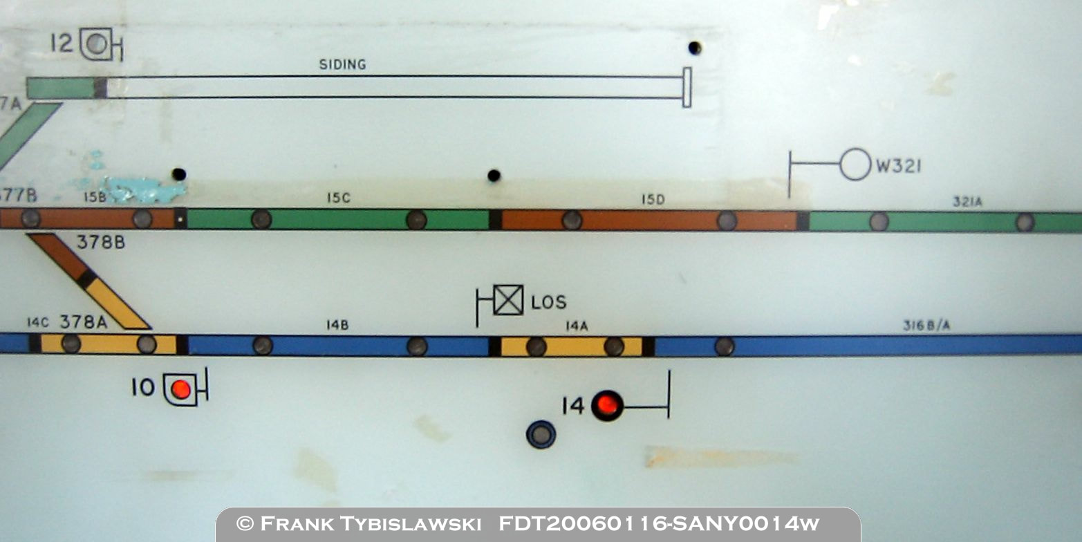
Above: The Siding at the Ebbw Vale end, out of use by 2006, with holes drilled in the panel to fit a plastic plate over the siding to cover it and signal BA12. Signals BA10 and BA14 are both shown at 'stop' and W321 signal (not repeated on the panel) is also in view. The Limit of Shunt on the Up Road is also shown between 14A and 14B tracks. The Down Siding was a generous 500m in length and towards the Ebbw Vale end sloped down towards road level.
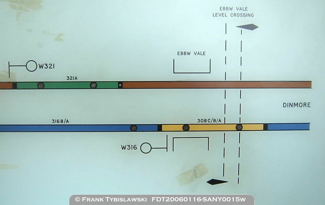
Above: The right hand edge of the panel shows Ebbw Vale platforms and signal W316 on the Up Road. The level crossing only provided access to a clay pipe factory which is now closed. The track circuit indication on the Up Road at Ebbw Vale is labelled as 308C/B/A and represents three track circuits which in reality stretchs about half-way to Dinmore's Up platform.
|
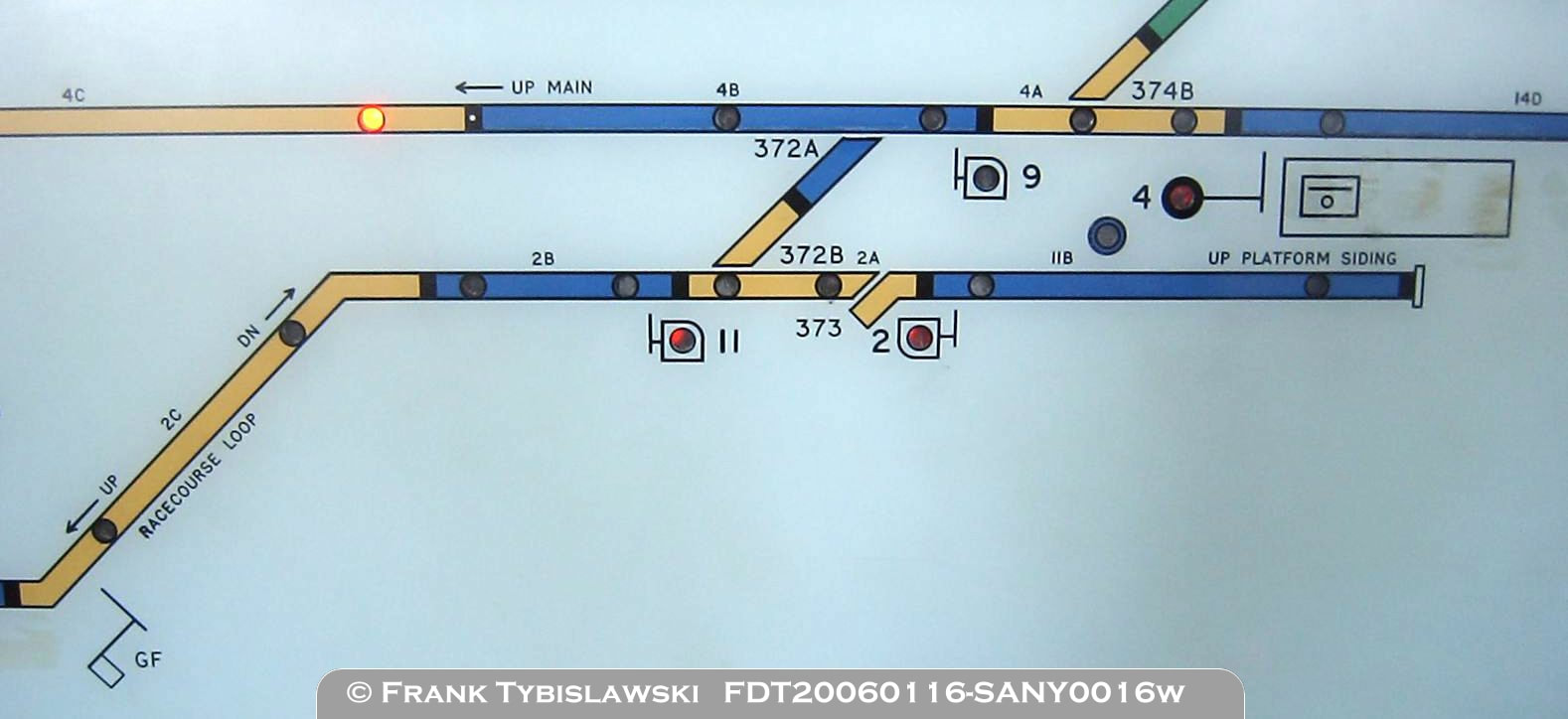
Above: The Up Platform Siding, which also had a platform for connecting with railmotors to Bundamba Racecourse is fully track circuited, and catch points No.373 protect No.372 crossover and prevent any rollingstock running down the steep grade towards Bundamba Racecourse. Shunt signals BA11 and BA9 are used for both running and shunting movements. Signal BA2 is unusual as it allowed a railmotor to proceed to Bundamba Racecourse platform as a shunting move.
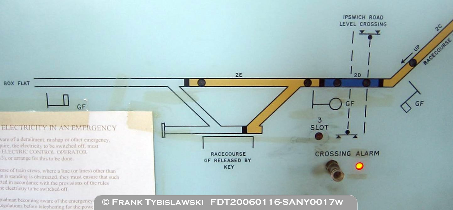
Above: The lower left-hand edge of the panel shows the branch line to Bundamba Racecourse, which continues to Box Flat and Swanbank. Bundamba Racecourse could be opened as a staff station and the Up and Down semaphore signals (normally at proceed) are both shown on the panel. The branch Home signal BA3 is shown although the panel indication BA3 SLOT is drawn adjacent to the signal. Note that the level crossing is labelled as 'Ipswich Road' when it is actually 'Brisbane Road'. For consistency this error is repeated on the replica panel. The Crossing Alarm indication for Ipswich Road (and also the Ebbw Vale level crossing) was never explained to me, the lamp would flash at times and the station staff would press the button to acknowledge it. I decided not to replicate this on the replica panel as it offered nothing towards operation of the panel and simulations of working trains through Bundamba, and only complicated construction.
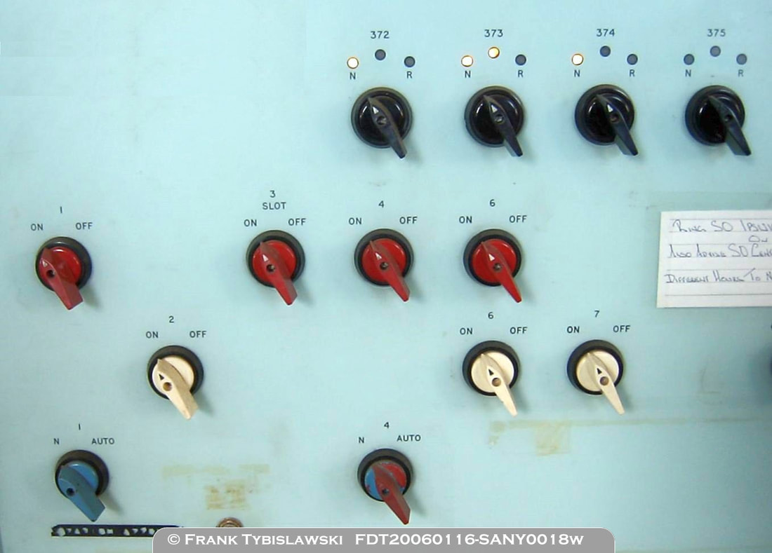
Above: The left hand part of the central switch panel showing the point switches on the top row, main signal switches on the second row, shunt signal switches on the third row, and the 'Auto' switches on the bottom row. Note that some signals have switches that appear on two or three rows. Also note the labelling of signal BA3 as '3 SLOT'. Again note No.375 points normal (N) indication bulb has blown. No.373 points are showing 'free' with the centre light lit. Signal No.5 does not exist nor is there space for a switch to be added.
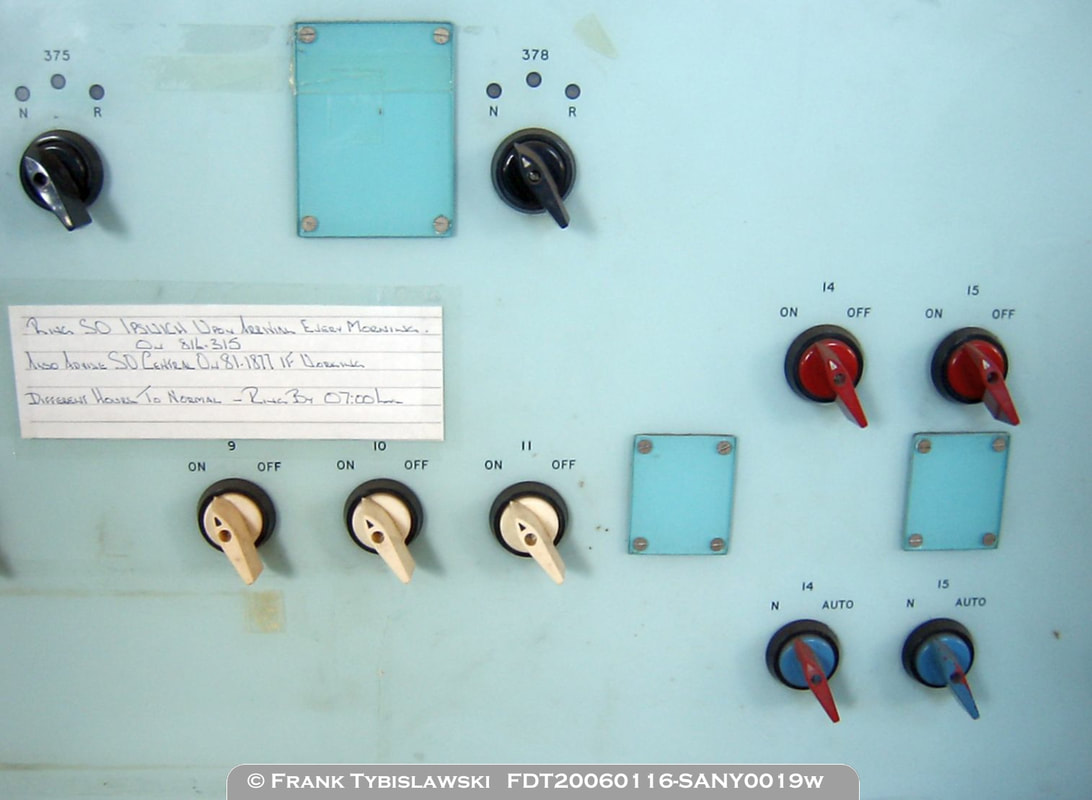
Above: The right hand part of the central switch panel showing the other switches for points and signals. No.377 points have been removed and the switch has been removed. Note that there is a space for a set of points numbered 376 and a gap where the switch could be added, and there is also a gap where a signal numbered BA8 could have a switch added. The switch for signal BA12 (Shunt from Siding via No.377 points) has also been removed. Signal BA13, like signal BA5 above, does not exist nor is there space for a switch if it was ever added. The switch for the Shunt signal on signal BA15 has also been removed which I feel is an error as BA15 Shunt still exists and can be used to shunt from the Down platform to the Down Limit of Shunt on the Up line.
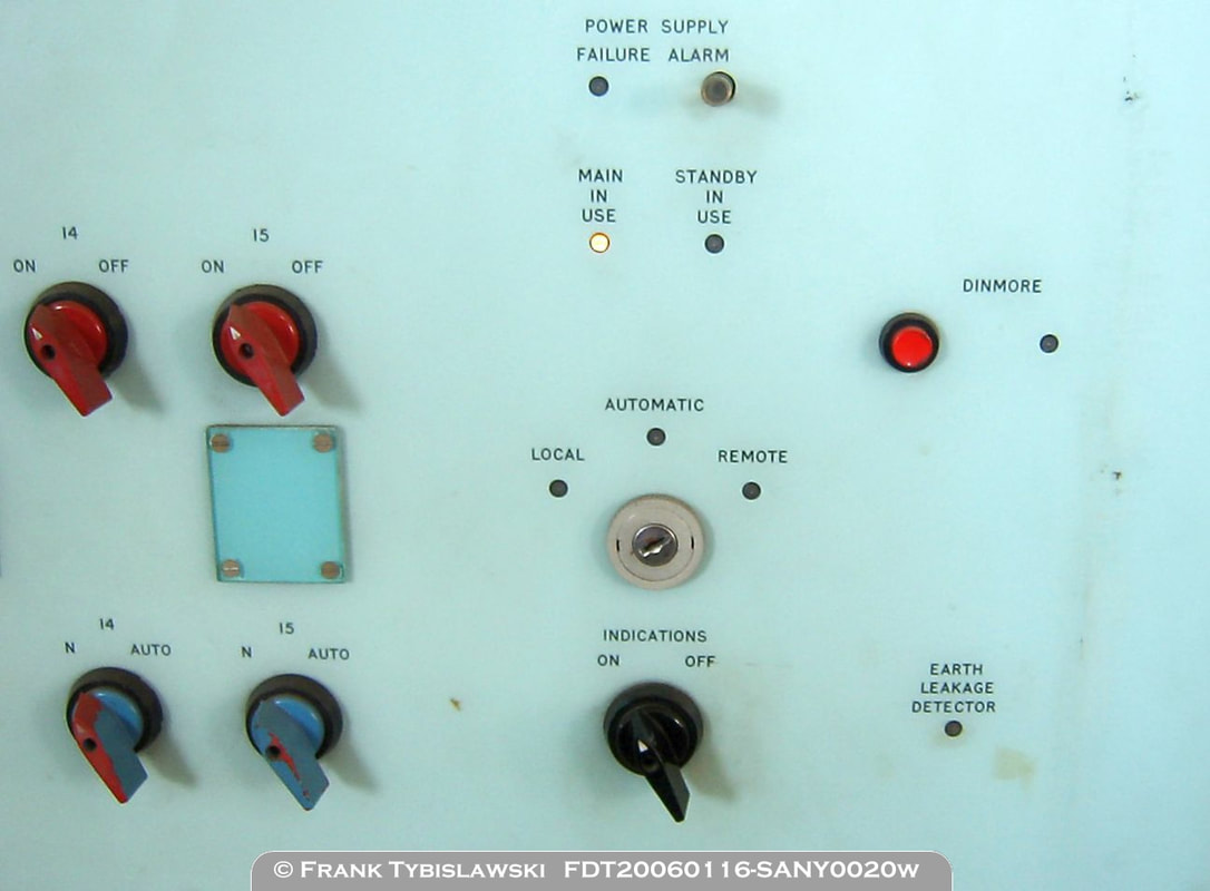
Above: The right hand edge of the switch panel has a two-position switch to turn all panel indications on or off, and this will be replicated on the replica panel. Above that is the three-position key switch to control the operation of the panel. Only the 'Local' and 'Automatic' positions will function on the replica panel. To the right of this is the Block Bell button and indication lamp for Dinmore, a similar set exists on the opposite side for Ipswich. The Power Supply Failure Alarm indication, reset button, and indication lamps will not be repeated on the replica panel.
|
Above: A rare image of the reverse side of the panel facia showing the wiring to the switches and indication lamps. All the wiring is routed via ducting to the edge of the panel where the wiring loops to the body of the panel. The position of the Up and Down main lines and branch line are obvious towards the top part of the panel. The rotary switches can be seen in the bottom section of the panel and also evident are the three switches that have been removed and blanked over. Note the heavy steel construction used throughout.
|

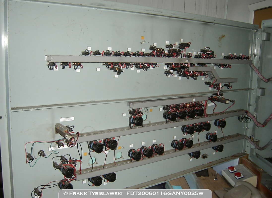
Above: Another rare image showing the internal cabling in Bundamba's local signal panel. Wiring from the switches and indication lamps are connected to terminal strips, the opposite side of the terminal strips have the cables connected back to the Relay Room on the Down platform. The wires appear to be arranged into groups (perhaps of similar types/functions), some with direct connections, some appear to have fuses or removable pins for testing purposes.
|
prototype photos & data:
extras.
|
|
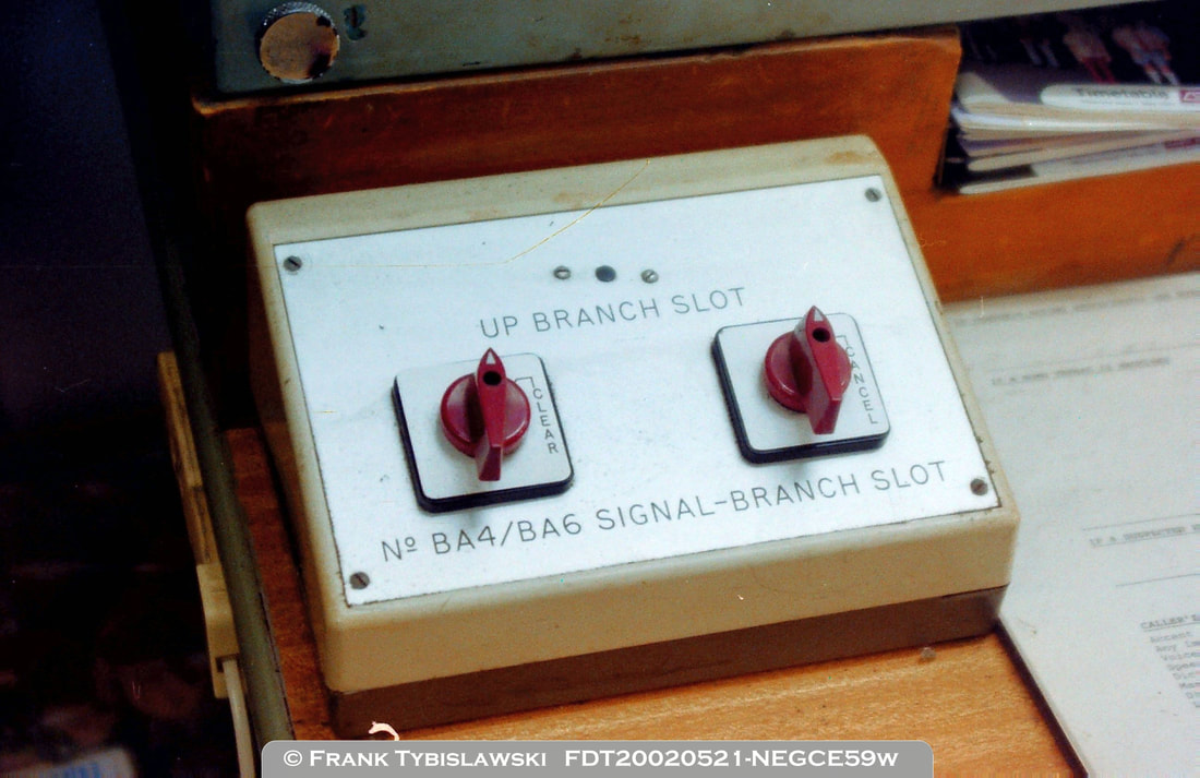
|
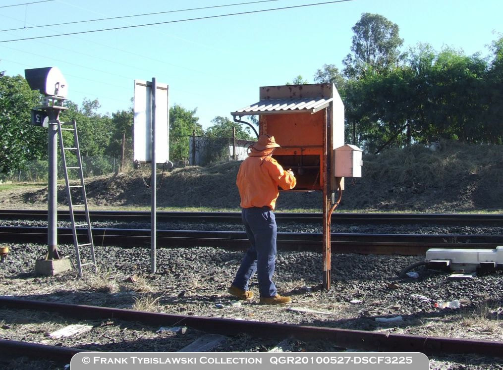
Above: Although not part of the actual panel, or part of the project to replicate the panel, these are the Slot switches provided on the 22nd of April 1985. The Slot switches allowed trains to work to the Swanbank Branch without the panel being cut-in. After the safeworking had been prepared by the Station Staff, and the route set remotely from Mayne Control Centre, the switch could be turned to clear the final signal (BA4 or BA6) to a 'proceed aspect'. If Bundamba was unattended, train crew would use the key-switches provided to perform the same function after they had collected the Ordinary Staff or Train Ticket to proceed onto the branch.
|
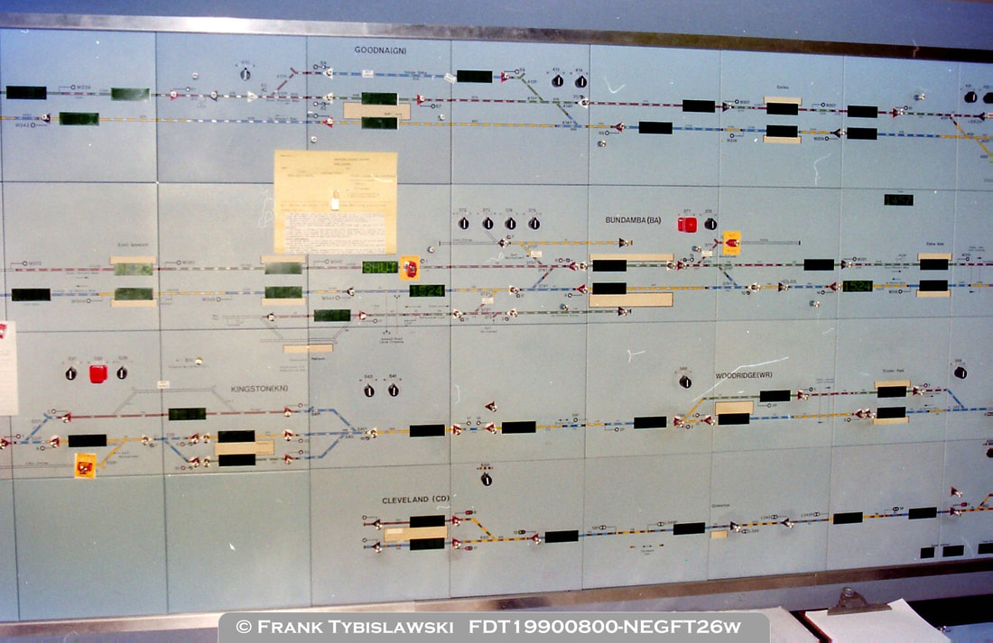
Above: This is part of the old Mayne Control Centre panel which shows Bundamba and stations around it also controlled by the same signalman. The Down Main Line is closed for a track possession and the Down Siding at the Brisbane end is also still closed. The small white rectangles on some points or crossovers indicated that they were 'unwired' routes and were not available to electric trains. What can't be seen in the image, but the panel reveals, is that No.373 catch points, No.375 crossover, and No.377 points & catch points were self-normalising.
|
key dates.
|
Date
24-8-1980
20-9-1980 21-12-1982 6-1-1983 21-3-1984 10-5-1984 3-1985 22-4-1985 22-12-1985 22-8-1986 -- 6-7-1991 8-7-1991 9-9-1991 4-7-1992 3-7-1993 2-7-1994 11-2-1995 29-3-1996 16-9-1999 -- 13 & 14-6-2000 11-3-2002 --- 1-12-2013 --- 14-5-2020 |
Change
Bundamba colour light signalling & panel commissioned.
Darra to Ipswich electrification commissioned. Box Flat export coal balloon loop commissioned. First export coal train from Box Flat to Fisherman Islands. Signal control transferred to Mayne Control Centre, panel could be cut-in if required. Bundamba Racecourse RM shuttle ran with a DEL hauled train to Brisbane after the last race. Coal trains renumbered to #95xx and 98xx. BA4/BA6 Slot switches provided. Sperry car ran to Box Flat this day. Bundamba-Box Flat became a Staff Only section. -- Bundamba Racecourse special RM's ran on this day. Half-consist export coal train (one loco + 19 VAO) ran (8-7-1991 to 10-7-1991). Staff & Ticket working re-introduced between Bundamba and Box Flat. Bundamba Racecourse RM's ran a shuttle service for Ipswich Cup. Bundamba Racecourse RM's ran a shuttle service. Bundamba Racecourse RM's ran a shuttle service. First Macalister to Swanbank coal train ran. Tobacco for Bundamba attached to train ex Mareeba. No.375 crossover to Tobacco Sidings clipped and locked out of use. -- QPSR running Box Flat to Bundamba Racecourse. Macalister/West Moreton coal trains extended from 39 to 41 wagons --- No.375 crossover, signal BA7 and Down Sidings removed by this date. --- Artwork for replica panel send to manufacturer. |
